Abstract: This article introduces the structural characteristics, working principles, auxiliary power supply, and wiring methods of wheel-spoke load cells, and analyzes the issues that should be noted in practical applications. It is of great significance to promote the application of wheel-spoke load cells in the field of industrial process control.
Keywords: structural characteristics; auxiliary power supply; wiring methods
A load cell is a device that converts weight signals or tensile and pressure signals into measurable electrical signals and outputs these electrical signals. With the continuous development of sensor technology and information technology, load cells have also made rapid advancements. Only by understanding the structural characteristics, working principles, and issues to be noted in practical applications of load cells can we better apply them in the field of industrial process control and promote industrial development.
1 Classification of Load Cells
Load cells can be classified into various types based on their conversion methods, including capacitive, hydraulic, and strain gauge types. Among these, strain gauge load cells are the most widely used due to their high accuracy, wide measurement range, and good frequency response characteristics. Strain gauge load cells can be further classified into wheel-spoke, beam, bridge, and ring types. The wheel-spoke load cell (hereinafter referred to as the wheel-spoke sensor) is widely used in various industrial process control fields due to its strong resistance to lateral forces and eccentric loads, low center of gravity, ease of installation, simple and robust structure, good linearity, repeatability, and overload capacity.
2 Structure and Working Principle of Wheel-Spoke Sensors
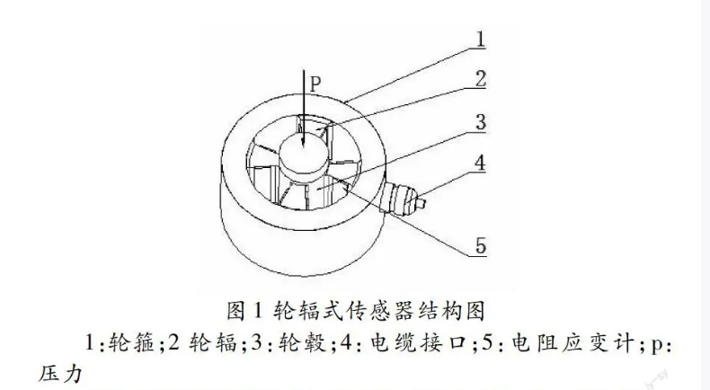
The wheel-spoke sensor mainly consists of a wheel rim, hub, and spokes, as shown in Figure 1. The hub bears the load and transmits the load, the wheel rim supports the load, and the spokes connect the wheel rim and hub. Strain gauges are bonded to the center positions on both sides of each spoke, and the spokes are usually symmetrically distributed in pairs.
Wheel Rim: 2 Spokes: 3 Hub: 4 Cable Interface: 5 Strain Gauge; p: Pressure 1:
Typically, the wheel-spoke sensor is used in conjunction with a load display instrument (hereinafter referred to as the instrument), which can directly display the weight of an object. Its working principle is as follows: when the object to be weighed is placed on the wheel-spoke sensor, the strain gauge on the spokes deforms, and the load cell converts the weight into a corresponding mV-level electrical signal according to a certain functional relationship. This signal is then processed through pre-amplification, filtering, and A/D conversion, and is directly displayed on the screen as the weight of the object.
3 Auxiliary Power Supply for Wheel-Spoke Sensors
As mentioned in the working principle, the wheel-spoke sensor needs to convert the weight signal into an electrical signal and output it. The output signal requires an external power supply to provide energy. When used with an instrument, the energy required for the output electrical signal is provided by the instrument. Since most instruments use a 220V AC power supply and the voltage has a wide allowable variation range, it can be directly powered by a 220V source when used with the instrument.
Sometimes, the wheel-spoke sensor is also used with a transmitter, in which case the energy required for the output electrical signal is provided by the transmitter. Since the power supply for transmitters is generally 5V, 12V, or 24V, when used with a transmitter, it cannot be directly connected to a 220V or 380V power supply. A switching power supply must be used to convert the high voltage into a stable low voltage for normal operation.
4 Wiring Methods for Wheel-Spoke Sensors
Wheel-spoke sensors typically have two wiring methods: four-wire and six-wire systems. The four-wire method is more commonly used when the cable length is short, as it does not impose special requirements on the instrument and is convenient to use.
When the wheel-spoke sensor is used with a transmitter, a switching power supply is required for voltage reduction. In this case, four wires are drawn from the transmitter cable connector, colored red, black, white, and green. The red and black wires are the power supply lines, connected to the red and black lines of the switching power supply; the white and green wires are the signal lines, connected to the host computer to collect the output signal, which is monitored and processed through the host computer.
5 Issues in the Application of Wheel-Spoke Sensors
5.1 Load Range of Wheel-Spoke Sensors
Generally, the closer the load range of the sensor is to the load it bears, the higher the weighing accuracy. If the mass of the object to be weighed is relatively light (for example, 10T), but a sensor with a larger load range (such as 50T) is selected, the resulting numerical error will be significant. In practical applications, it is also necessary to consider the impact of eccentric loads, vibrations, and shocks on the sensor. Therefore, if the selected load range is too small, it may damage the sensor. Thus, various influencing factors must be considered when selecting a sensor to ensure its normal operation and extend its service life. Additionally, when the wheel-spoke sensor is used with an instrument, since the instrument is a general-purpose device (with multiple load ranges), the appropriate load range must also be selected for the load cell. If an inappropriate range is selected, the staff may misjudge and misoperate the collected data, which could severely damage the load cell.
5.2 Working Environment of Wheel-Spoke Sensors
As the technology of wheel-spoke sensors continues to mature, their requirements for working environments have become more relaxed. However, in practical applications, we still need to consider the impact of the working environment on the sensor, such as dust and humidity, which can cause short circuits; highly corrosive environments can damage the elastic elements of the sensor or cause short circuits. Therefore, while ensuring the accuracy of the sensor, we should take measures to avoid adverse effects from harsh working environments. For example, in dusty and humid environments, the sensor can be completely sealed using welding or other methods, and the upper part can be made into an arc shape to ensure uniform stress. Additionally, when size permits, a protective layer can be added to the outside of the sensor to reduce the adverse effects of the external environment on the sensor.