The microcontroller is the core component of embedded systems, and circuits using microcontrollers are much more complex. However, when modifying and adding new features, circuits with microcontrollers are easier to implement, which is why electronic devices use microcontrollers. So, what are the challenges to pay attention to in the design of microcontroller circuits?
1. Selection of Pull-Up Resistors for Microcontrollers
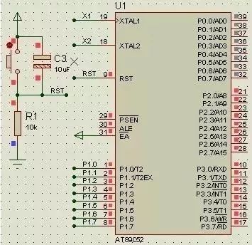
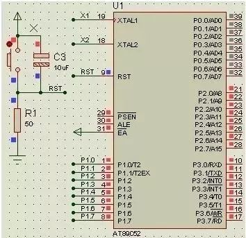
As we can see, when the resistor R1=10k, the RST pin is high, while when R1=50, the RST pin is low. Clearly, R1=10k is incorrect, as the microcontroller remains in a reset state and cannot function at all. This occurs because the RST pin contains a transistor, which allows a small cutoff current even when in cutoff state. When R is very large, the weak cutoff current can create a high level.
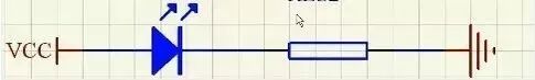
2. Calculation of Series Resistors for LEDs
Typically, for red surface mount LEDs: the voltage is 1.6V-2.4V, and the current is 2-20mA. Brightness varies between 2-5mA, and remains relatively constant above 5mA.
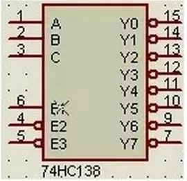
3. Insufficient Ports
In this case, expansion chips can be used, such as the 74HC138 decoder for expansion.
4. Filter Capacitors
Filter capacitors are divided into high-frequency and low-frequency filter capacitors.
1. High-frequency filter capacitors are generally 104 (0.1uF), aimed at short-circuiting high-frequency components to protect devices from high-frequency interference. Ordinary ICs should have these capacitors between power and ground to eliminate high-frequency interference (such as electrostatic discharge).
2. Low-frequency filter capacitors are typically electrolytic capacitors (100uF), aimed at removing low-frequency ripple and storing some energy to stabilize the power supply. These are mostly connected at the power interface, near high-power components, such as: USB ports, stepper motors, and 1602 backlight displays. The voltage rating should be at least twice the maximum system voltage.
5. The Role of Transistors
1. Switching Function:
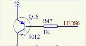
When LEDS6 is high, it is off; when low, it is on.
Calculating the current-limiting resistor: If the collector current is I, then the base current is I/100 (this involves amplification, where the collector current is 100 times the base current), with a PN junction voltage of 0.7V, R=(5-0.7)/(I/100)
2. Amplification Function: The collector current is 100 times the base current.
3. Level Conversion:
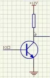
When the base is high, the transistor conducts, grounding the right-side wire to low; when the base is low, the transistor is off, outputting high.
6. Issues Related to Seven-Segment Displays
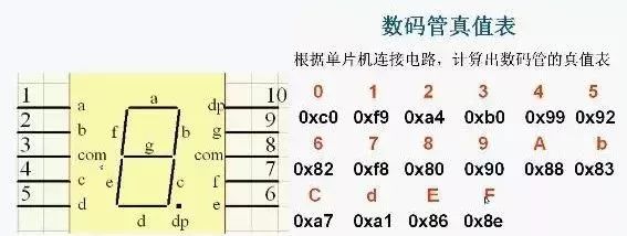
The digits formed by lighting the seven-segment display consist of a, b, c, d, e, f, g, and dp (decimal point), as shown in the truth table above.
7. Current and Voltage Drive Issues
Due to the limited output of microcontrollers, when there are many loads, additional driver chips are needed, such as the 74HC245.
8. Pull-Up Resistors
Principles for selecting pull-up resistors:
1. To save power and consider the chip’s sinking current capability, the resistor should be sufficiently large; a larger resistor means lower current.2. To ensure sufficient driving current, the resistor should be sufficiently small; a smaller resistor means higher current.3. For high-speed circuits, excessively large pull-up resistors may cause the edges to become sluggish.In summary: Pull-up resistors are commonly selected between 1K and 10K, and the same applies to pull-down resistors.
Pull-up and pull-down resistors are used to set uncertain signals to high or low levels through a resistor.
1. Level conversion, improving output level parameters.2. OC gates must have pull-up resistors to function.3. Increase the driving capability of ordinary IO pins.4. Pull-up and pull-down on floating pins to resist interference.
9. Crystal Oscillator and Reset Circuit
Crystal Oscillator Circuit
1. Crystal selection: Choose based on actual system requirements, such as 6M, 12M, 11.0592M, 20M, etc.
2. Load capacitance: Connect two 10 to 30pF capacitors to ground, commonly 20pF.
3. Measuring the crystal with a multimeter: Directly connect the red probe to the crystal pin and the black probe to GND to measure the voltage.
Reset Circuit
Sets the internal circuit of the microcontroller to a defined state, initializing all registers.
The reset time for the 51 microcontroller is approximately 2 machine cycles, but this depends on the chip’s datasheet.
Typically, this is done through a reset chip or reset circuit, with specific resistor-capacitor parameters calculated via Google search.
10. Key Bounce and Elimination
Keys are also mechanical devices, and when pressed or released, they can produce bounce, as shown in the figure below:
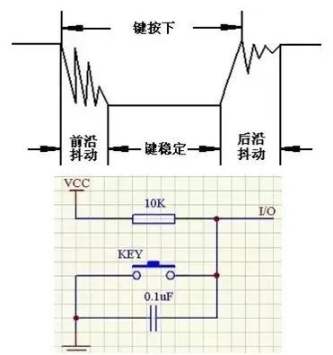
There are two methods to eliminate this: software debouncing and hardware debouncing, where hardware debouncing uses capacitors to short high-frequency signals.
Software debouncing detects the key closure and executes a delay program, creating a 5ms to 10ms delay to allow the front edge bounce to disappear before checking the key state again. If it remains closed, it is confirmed that the key is genuinely pressed.
Source: Internet, copyright belongs to the original author. If there are any copyright issues or questions, please contact us immediately. Thank you.
Read Again
Project Practice | [Case Analysis] Why Can’t the Crystal Oscillator Be Placed at the Edge of the PCB?
Project Practice | [Essentials] How to Solve Power Port CE/RE Issues
Project Practice | Detailed Explanation of Switching Power Supply EMI Modules
Project Practice | Using Wire to Make a “Circuit Board”, You Can’t Help but Admire This Move!
Technical Sharing | Things to Know About Switching Power Supplies
Technical Sharing | PCB Grounding Design Specifications Worth Watching!
Technical Sharing | Must-Have | 15 Golden Rules for Allegro Software!
Technical Sharing | PCB Experts Say, Let You Quickly Understand CAD
Live Broadcast Preview | Covering Four Major Themes, Easily Master Antenna Array Design Technology!
Live Broadcast Review | [Live Preview] Introduction to Converting PCB Files Between Different Software
Live Broadcast Review | [Public Welfare Live] What is the Importance of DFM in PCB Design?
Live Broadcast Review | Free Learning! Practical Design of USB Network Card Based on Cadence
Skill Improvement | The First Practical 5G Mobile Phone Antenna Design Course Online!
Skill Improvement | A Power R&D Engineer with Over Ten Years of Experience Teaches You!
Skill Improvement | [Disciple Program] One-on-One Online Teaching with Famous Teachers
Skill Improvement | PCB Industry Benefits, First Domestic DFM Manufacturability Design Analysis Software “Free” to Use
 Fanyi Classroom (www.fanyedu.com) is an open electronic learning and technical Q&A platform under Fanyi, including electronic design technology courses, Fanyi Q&A, technical publications, and live broadcasts by famous teachers, spanning knowledge sharing and online education. The content covers embedded systems, microcontrollers, power design, analog technology, PCB design, PCB simulation, software development, Lab applications, IC design, and other subfields, gathering hundreds of online teachers to build a professional electronic learning ecosystem through the platform’s online teaching classrooms, facilitating boundary-less communication for electronic industry students.
 Register now on the APP to receive 1888 yuan Fanyi Classroom VIP
Click here to read the article again↘