
Why do we need pull-up resistors in I2C?
Because it uses open-drain output.
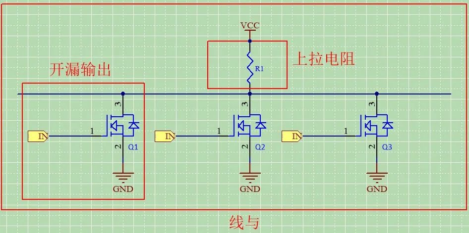
Why is it open-drain output?
The I2C protocol supports multiple master devices and multiple slave devices on a single bus. If push-pull output is used instead of open-drain output, it could lead to short circuits between master devices. Therefore, the bus generally uses open-drain output.
Why do we need pull-up resistors?
Pull-up resistors are needed because I2C communication requires the ability to output a high level.Generally, open-drain output cannot output a high level. If a pull-up resistor is connected to the drain, level conversion can be achieved.I2C consists of two buses, SDA and SCL. The output stage of devices connected to the bus must be open-drain, all connected to the power supply through pull-up resistors, which allows for the “wired AND” function. When the bus is idle, both lines are at a high level.
How to determine the value of the pull-up resistor?
Generally, the driving capability of IO ports is in the range of 2mA to 4mA.The resistance value cannot be too small:Power consumption issue. If the pull-up resistor value is too small, the current flowing into the port from VDD will be large, leading to high power consumption, which will increase the low level output value of the port (the I2C protocol specifies that the maximum allowed low level output value is 0.4V). Therefore, the pull-up resistor should typically be selected to be no less than 1K (when VDD = 3V, the current flowing in does not exceed 3mA).The resistance value cannot be too large:Speed issue. It depends on the pull-up resistor and the line capacitance forming an RC delay. The larger the RC delay, the more the waveform deviates from a square wave towards a sine wave, reducing the probability of correct data read/write. Therefore, the pull-up resistor cannot be too large.The load capacitance on the I2C bus must not exceed 400pF. As the number of devices on the I2C bus increases, the bus load capacitance also increases. When the total load capacitance exceeds 400pF, reliable operation cannot be guaranteed. This is also a limitation of I2C.It is recommended to use pull-up resistors of 1.5K, 2.2K, or 4.7K.
Basic Operations of the I2C Bus
According to the I2C bus specification, both lines must be high when the bus is idle.Assuming master device A needs to start I2C, it must pull SDA from high to low while SCL is high to signal the start.After pulling SDA high, master device A needs to check the level of SDA. Why? Because of wired AND; if master device A pulls SDA high while another master device has already pulled SDA low, since 1 & 0 = 0, when master device A checks the SDA level, it will find it is not high but low. This indicates that another master device has taken control of the bus before it, and master device A must give up the bus. If SDA is high, it means master device A can take control of the bus, and then master device A pulls SDA low to start communication.Therefore, when simulating I2C, the GPIO port must be set to open-drain output with pull-up resistors.*This article is a network repost, and the copyright belongs to the original author. If there is any infringement, please contact for deletion.