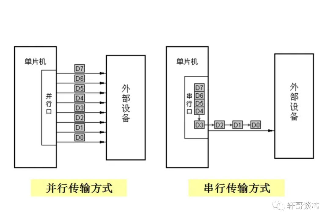
Many engineers who started learning with the 51 microcontroller might feel a bit confused by this question. How can a parallel interface, which can send a large amount of parallel data, be slower than a serial interface? The 51 microcontroller also has a parallel port, which is used for driving LCD screens and connecting external RAM, while the serial port is just 115200bps.
In fact, UART is just one instance of a serial interface; there are many forms of serial interfaces. In today’s article, we will systematically look at why serial interfaces can be faster than parallel ones.
First, high-speed serial ports do not require a clock line to synchronize the data stream. Without periodic clock edges, the spectrum is not concentrated, which significantly reduces noise interference. For example, in PCIE and SATA, clock information is integrated into the data stream through 8b/10b encoding. The data itself is scrambled, ensuring that there are never long strings of more than five consecutive 0s or 1s (which aids clock recovery), and there is absolutely no periodicity (to avoid spectrum concentration). Thus, the clock can be recovered directly from the edges of the data stream using PLL, and the recovered clock can then be used to sample the data stream. What are the benefits of this? Clock signals consume a lot of power and generate the most noise. By not transmitting a clock, we can reduce power consumption and noise.
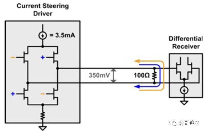
Secondly, all high-speed serial ports use differential signaling for transmission. External noise is simultaneously loaded onto both differential lines, and by subtracting them, it can be canceled out, providing strong anti-interference capability. Moreover, because differential lines typically transmit using current as the carrier, there is no voltage drop at the far end, making long distances less of an issue.
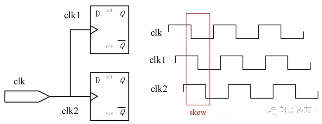
Furthermore, differential signals do not have clock skew issues because there is no synchronized clock at all, eliminating the need for alignment between the clock and the data stream. We only need to ensure that the differential signal lines are aligned, which is quite easy because the values of the differential signal lines are always opposite, leading to strong correlation and easy control. When one line transitions, the other line will transition shortly after with a delay from a NOT gate, which is easy to compensate. The biggest problem with parallel buses is that when multiple lines are transmitting, it is impossible to guarantee that all transitions are aligned. It is very likely that some signals will lag behind by one T, resulting in incorrect data transmission. Controlling this is also difficult because the signals have no correlation; the transitions of each signal are independent. Due to different wiring, one line may transition early while another transitions late, and with different resistances and noise on each transmission line, it becomes impossible to determine which value corresponds to which cycle after a while.
In addition, fewer differential lines result in less interference. In parallel transmission, there are generally 32 or 64 lines. When one line transitions, it can introduce noise to adjacent lines, and the higher the frequency, the greater this noise, which can easily lead to other line values being corrupted or unrecognizable. Therefore, high frequencies are not feasible. Serial transmission typically uses just four data lines, divided into two differential lines for Rx and two for Tx. The differential lines always transition in opposite directions, canceling out their respective transition noise. For example, when the positive polarity of Rx transitions, the noise generated can be directly canceled out by the negative polarity of Rx with its opposite transition (since they are differential signals). The total noise is zero, eliminating internal noise.
In summary, the various advantages of serial transmission make it immune to both internal and external noise, and there is no concern about signal alignment, allowing for extremely high transmission rates. For instance, SATA can transmit data streams at rates of 6Gb, and PCIE can do so at 8Gb. Such rates are simply unattainable for parallel transmission, not to mention that serial transmission can save a significant number of pins.
To improve the transmission rate of a single line, we must mention the three key tools of our analog circuit engineers: differential signaling, Clock-Data Recovery (CDR), and Channel Equalization (Eq).
The benefits of differential signaling include strong anti-interference capability and relatively low noise introduction. Although it requires two lines, increasing the speed from hundreds of M to several G is still worthwhile.
The advantage of CDR is that it eliminates skew and reduces the power consumption and noise of the clock (though it introduces the power consumption and noise of the CDR circuit itself). It also avoids electromagnetic interference. Just imagine transmitting a 15G clock on a PCB or a wire; that would be quite impressive, but thankfully we don’t have to do that.
Channel Equalization deserves special mention as it is a decisive factor in the rapid development of SerDes, so I will spend some words discussing it.
Generally, real-world channels have low-pass characteristics, with small capacitances everywhere. The molecules in insulators absorb electric field energy at high frequencies, and the skin effect in metal wires means that high-frequency signals cannot travel far without becoming distorted. For example, the frequency characteristics of a certain channel are shown below (green line).
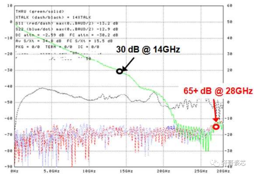
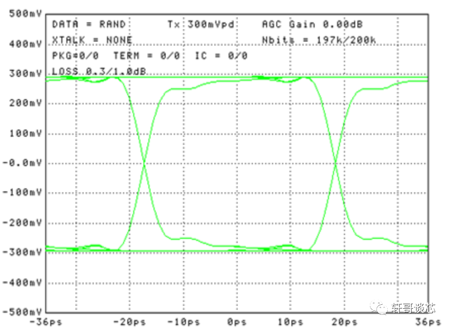
As shown in the figure, at the frequency point corresponding to 28Gbps, the signal energy is attenuated by 30db, and the voltage amplitude is only 3%; at the frequency point corresponding to 56Gbps, it is even worse, with 65db indicating that the signal voltage swing is less than one-thousandth. In such a channel, a perfectly beautiful eye diagram at the transmitter:
At the receiver end, it turns into a pile of garbage:
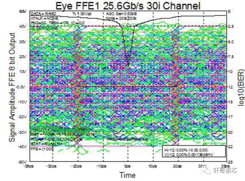
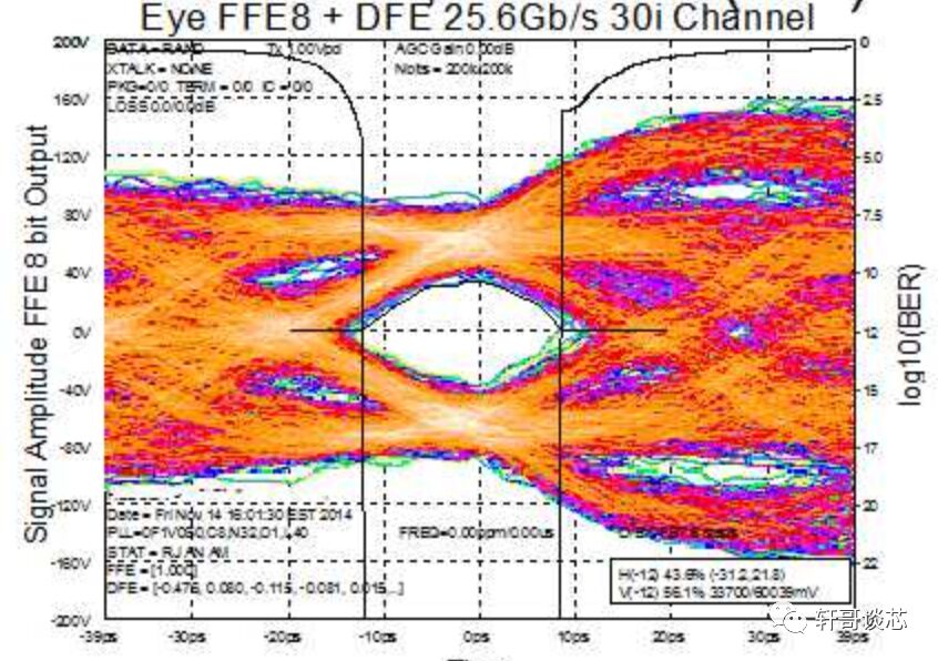
Nothing can be recognized, right? However, after our clever engineers put in a lot of effort, once the equalization switch is turned on, the signal becomes like this:
So can these three optimization measures be applied to parallel ports?
There is no need to mention differential transmission; parallel ports already have enough wires, and doubling the number would lead to chaos. System engineers would be furious.
The significance of CDR is also minimal; after all, the speed of the parallel port is not high. It is much simpler to transmit the clock along with a bunch of data lines than to implement CDR at the receiver to resample each data bit.
Channel equalization is a dragon-slaying technique. Without differential signaling, parallel transmission would only reach a few hundred M; there’s no attenuation to worry about, so why bother? It’s better to consider various issues related to noise crosstalk.
Therefore, why is serial communication faster than parallel communication? It is because the characteristics and application scenarios of serial communication make it more suitable for adopting design methods that can enhance the rate of a single channel, which are not appropriate for parallel communication.
From the current applications, those requiring sustained and stable high bandwidth often use high-speed serial interfaces. If one channel’s bandwidth is insufficient, additional channels are added. This is the case for various video network applications. Meanwhile, some legacy applications with lower speeds and those requiring burst high bandwidth still use parallel communication, such as some special DDR. Although new standards like XDR/GDDR/HMC/HCM are attempting to introduce SerDes, the peculiarities of the DRAM industry allow parallel communication to continue to exist.