Source: Today’s Optoelectronics
Original Author: Xiaoxing Wang
How to select TIA chips for optical modules? Should we continue using the model from the previous project or follow the recommendations of the FAE? What parameters should we focus on for high-speed TIA chips?
High-speedTIA chips are core components in optical modules and have always attracted significant attention. However, there are many detailed parameters, categories, and terminologies. Common chip specifications can easily exceed ten pages, making it difficult to grasp the key points. Today, we will unveil the intricacies of high-speedTIA chips and analyze how to interpret various parameters and curve graphs in chip specifications.
1. Data Rate
When you open the specification sheet or look at the main title on the chip manufacturer’s webpage, you will see descriptions regarding the TIA data rate:
·Low-Power, 28-Gbps, 4-Channel Limiting TIA
This allows engineers to quickly identify that the chip is suitable for applications with electrical port rates of28-Gbps or25Gbps, such as common100G Ethernet optical modules or100G BASE-LR4,OUT-4 and other optical modules.Data rate refers to the bit rate, which is the number of bits transmitted per second, representing the electrical port rate of the optical module. There is also baud rateGaud, which indicates the number of symbols transmitted per unit time. The bit rate differs from the baud rate; for example, in theNRZ encoding format, the bit rate equals the baud rate. However, in thePAM4 encoding format, the bit rate equals twice the baud rate.However, the data rate (bit rate) is not the most direct parameter of the amplifier. The data rate is merely a parameter marked by the chip manufacturer from the user’s perspective, aimed at facilitating the selection of optical modules. The chip indicates which rate it is suitable for based on complete testing done at that rate. The specific detailed DC and AC parameters are verifiable. The actual capability of the device to handle data rates is related to the bandwidth parameter.Next, let’s look at the bandwidth parameter.
2. Power Consumption
Why is power consumption important? Because the module’s power consumption is tested before leaving the factory, and the module’sSpec andMSA protocols clearly specify the power level of the module. Optical modules have been trending towards lower power consumption and smaller sizes. Therefore, the power consumption of the chip has become a significant concern in optical module applications.
Regarding power consumption, the homepage of the specification sheetFeature will have typical values indicated:
·139 mW per Channel
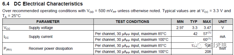
This typical value indicates that in a 4-channel TIA, the power consumption of a single channel TIA is approximately139mW. In addition to typical values, we can also look at theDC Electrical Characteristics table for descriptions ofICC andReceiver power dissipation. The table also shows the power consumption of the chip at85℃ and100℃, which is also very important. At high temperatures, the heat dissipation performance of the chip deteriorates, leading to increased power consumption. Optical modules also undergo high-temperature testing; during operation, the ambient temperature is often high. If the power consumption increases significantly at high temperatures, exceeding specifications, the product will not pass the testing standards.
For example, the power consumption comparison of the following variousIC is shown below.
|
MxL9101 |
GN1088 |
HXR44400 |
MATA-03101 |
ONET2804T |
|
|
Manufacture |
Maxlinear |
Semtech |
Renesas |
Macom |
TI |
|
Data rate |
28Gbps NRZ |
28Gbps NRZ |
56Gbps PAM4 |
28Gbps NRZ |
28Gbps NRZ |
|
Channel |
4 |
4 |
4 |
4 |
4 |
|
Per Channel Power Dissipation |
0.075W |
0.096W |
0.158W |
0.08W |
0.139W |
3. Bandwidth
Bandwidth is an AC parameter that characterizes the maximum frequency of signals that can be transmitted, usually represented by the frequency corresponding to a -3dB drop. For example, in the following figure, the -3dB bandwidth is21GHZ.
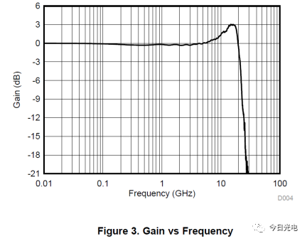
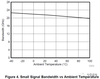
As mentioned earlier, the bandwidth parameter directly relates to the chip’s data rate. Only TIA chips with higher bandwidth can support higher-speed electrical signals. Why is this the case? For example, forNRZ signals, a28Gbps data rate requires a bandwidth of14GHZ. Of course, currently, many manufacturers of28Gbps TIA chips have bandwidths of21GHZ, providing a1.5 times margin to prevent3dB attenuation. Many people might ask, is a larger bandwidth margin better? A very high bandwidth margin is meaningless for the transmitter, but it can be a disadvantage for the receiver, as it introduces more noise. This will be discussed in the noise section below.Additionally, at high temperatures, the bandwidth of the TIA also decreases, as shown in the following figure. This means that high-frequency signals will experience attenuation at high temperatures. Therefore, it is necessary to check the impact of high temperatures on the chip’s bandwidth to prevent eye diagram issues in optical modules at elevated temperatures.
4. Noise
TIA is a special function operational amplifier, and when discussing operational amplifiers, we must talk about noise. The noise of operational amplifiers is a complex concept. Why is that? Senior engineers of TIA, Art Kay and Tim Green, have spent a lot of time analyzing and simulating operational amplifier noise mathematically, and even after reading it, one might feel confused. If you haven’t encountered it before, that’s okay; let’s briefly look at how several major manufacturers describe the noise of their respective TIAs:
|
MxL9101 |
GN1086 |
ONET2804T |
|
|
Manufacture |
Maxlinear |
Semtech |
TI |
|
Data rate |
28Gbps
|
28Gbps
|
28Gbps |
|
Channel |
4 |
4 |
4 |
|
Noise |
Input-referred 10pA/√Hz |
Input-referred 1.25uArms noise |
Input-referred 1.8uArms |
In fact, after reading this, one might still feel confused, as there are two units for noise description:pA/√Hz anduArms. Here, we will briefly explain. The former, picoamperes per square root of hertz, is the spectral density, representing the total noise within each 1Hz bandwidth, which equals the square root of the sum of the squares of each noise. For a 1Hz bandwidth, this value equals the noise magnitude, in picoamperes. The latter is the effective value of current noise, which is the integral of current noise within the effective bandwidth. The noise of TIA is typically expressed asInput-referred noise, which is the total noise divided by the gain. This value is usually provided with detailed testing conditions:
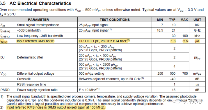
So, what impact does TIA noise have on optical modules? If the noise of TIA is relatively high, it means that the signal-to-noise ratio of TIA will be poor, and the voltage signal converted from the detected light will be inaccurate, leading to incorrect sampling outputs. This is especially true for small photocurrents; in small signal scenarios, the noise component becomes larger, making it difficult to accurately capture small signals. Some people say that the company has a lot of28G TIAs in stock; can they be directly applied to10G optical modules, as they share the same part number? This is not advisable. Not only is it more expensive, but TIAs with larger bandwidth also tend to have much higher noise. For example:
|
ONE8551T |
ONET2804T |
|
|
Manufacture |
TI |
TI |
|
Data rate |
11.3Gbps |
28Gbps |
|
Noise |
Input-referred 0.9uArms |
Input-referred 1.8uArms |
5. Input Saturation Current
High-speed TIA typically provides a parameter calledover load current, usually around3mApp. This saturation current value indicates the maximum input current of TIA. Combined with the sensitivity parameter of PD, it can be used to calculate the maximum detectable optical intensity.
6. Channel IsolationIn multi-channel TIAs, each channel is independent and integrated into one die. There is a parameter called isolation between each channel, which is usually greater than40db, indicating the noise impact of one channel on another during operation.
7. Die SizeAs the packaging of optical modules becomes smaller and the number of parallel channels increases, along with the internal optical components and connectors, the internal structure of optical modules becomes very compact. Therefore, when selecting chips, the size of the die is also a significant concern. Most high-speed chips useSige technology, which results in larger die sizes compared toCmos technology. Currently, the die size of a 4-channel TIA is typically around3.5mm*1.5mm, withGN1086 having a relatively advantageous area.
|
MxL9101 |
GN1086 |
HXR44400 |
ONET2804T |
|
|
Manufacture |
Maxlinear |
Semtech |
Renesas |
TI |
|
Data rate |
28Gbps NRZ |
28Gbps NRZ |
56Gbps PAM4 |
28Gbps NRZ |
|
Channel |
4 |
4 |
4 |
4 |
|
Die Size |
3.167mm x 1.672mm |
1.52mm x 1.1mm |
1.350mm x 3.370mm |
3.25mm × 1.45mm |
8. Other Functions: RSSI, AGC, Bandwidth Control, etc.
In addition to important parameters such as bandwidth, noise, power consumption, and die size, there are also some integrated functions that facilitate optical module design. For example:
·Gain Adjustment: By controlling the Pin, the mutual impedance can be adjusted to regulate the relationship between input and output, making it easier for users.
·Amplitude Adjustment: By controlling the Pin, the output amplitude can be adjusted to suit different signals.
·RSSI: The Received Signal Strength Indicator function allows for easy voltage sampling at the backend to monitor whether the received signal is overloaded or without light..

The reproduced content only represents the author’s views
It does not represent the position of the Semiconductor Institute of the Chinese Academy of Sciences
Editor: Jing Lingzi
Chief Editor: Jiang Yu
Submission Email: [email protected]
Previous Recommendations
1. The Semiconductor Institute has made progress in research on bionic covering neuron models and learning methods.
2. The Semiconductor Institute has made significant progress in inverted structure perovskite solar cells.
3. A comprehensive review of the history of semiconductor development in New China – “Through hardships for decades, the light boat has passed through thousands of mountains.”
4. What exactly is the 7nm process in chips?
5. Silicon-based integrated optical quantum chip technology.
6. How unusual is the quantum anomalous Hall effect? It may lead to the next revolution in information technology!