Introduction
Today, we will not cover the Zigbee protocol, but rather some operations of the timer in the CC2530 microcontroller.
This article uses 8-bit Timer 3 for experimentation, and other timers can be similarly applied.
Through this article:
-
You will learn some basic knowledge about timers.
-
You will see configuration instructions for some timer registers.
-
You will learn the thought process for calculating timing durations.
-
You will understand the principle of breathing lights and programming techniques.
1. Principle Analysis
1. LED Function
As shown in the schematic diagram, the operation of lighting the LED requires the P1.0 pin to be high, allowing the diode to conduct and light up the LED.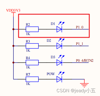
2. Breathing Light Principle
The basic principle of the breathing light utilizes the visual persistence of the human eye;
One fact to understand is that all the lights you see are actually flickering, but they flicker at different frequencies. Only those with a low flicker frequency are perceived as flickering effects, while those with a high flicker frequency appear as continuously lit.
For instance, when you use a phone to capture some LEDs, you will notice that the LED is constantly flickering, which is because the camera has a higher sensitivity than the human eye’s visual persistence.
The principle of the breathing light is similar; while maintaining a high frequency, we only need to change the time ratio of the LED being on/off, and our eyes will perceive it as the brightness of the LED.
The on/off ratio determines the brightness level.
As you might expect, when the on/off ratio is 1:0, it is the brightest moment; when the ratio is 0:1, it is the darkest moment, appearing as off.
The following square wave diagram can help you understand; assuming high level means on and low level means off, the cycle should be controlled within the persistence of vision of the eyes, modifying the duty cycle of high and low levels.

3. Timer Functions
1) Timer Input Capture Mode and Output Compare Mode.
-
Input capture mode, as the name suggests, is for capturing external signals. When the input on the relevant pin is captured, if the corresponding interrupt mask bit TxCCTLn.IM is set, an interrupt request will be generated.
-
Output compare mode (used today) is, as the name suggests, for output after comparison. If output is needed, the relevant pin must be set to output mode, such as the
ledpin used today.
2) Timer Counting Modes
-
Free running mode (used today) for an 8-bit timer 3 counts repeatedly from 0 to 0xff; conversely, a 16-bit timer 1 counts from 0 to 0xffff.
-
Counting down mode, relative to free mode, requires configuring a peak value register
T3CC0. After configuration, when the timer starts, it counts from the value inT3CC0to zero for a single count. To loop, it must be restarted from the timer interrupt execution program.
Note: The T3CC0 here is just the counting peak value needed for timer 3; the 16-bit timer 1 uses T1CC0L and T1CC0H.
-
Modulo mode counts from 0 to
T3CC0in a loop.
Note: When using this mode, timer 3 must be set to compare mode.
-
Counting up/down mode, as the name suggests, counts from 0 to
T3CC0, then fromT3CC0back to 0, looping continuously.
3) Related Register Configurations
-
T3CNT[SFR(0xCA)] Counting value register (read-only), shows the current internal counting value.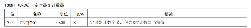
-
T3CTL[SFR(0xCB)]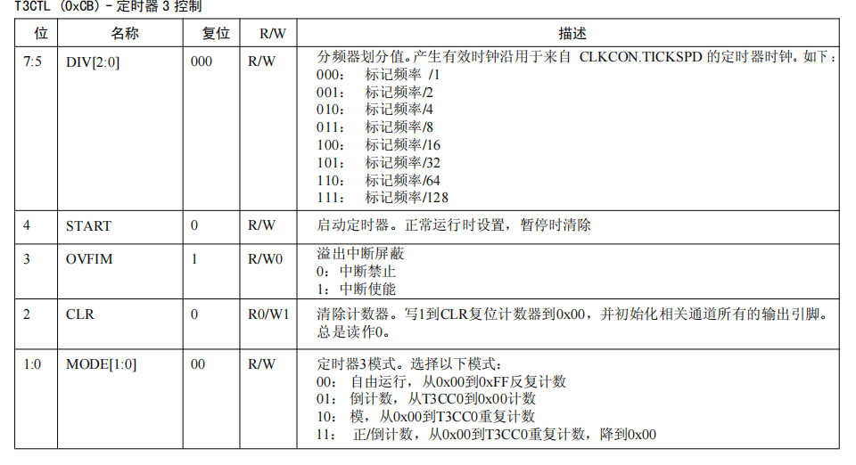
-
T3CCTL0[SFR(0xCC)]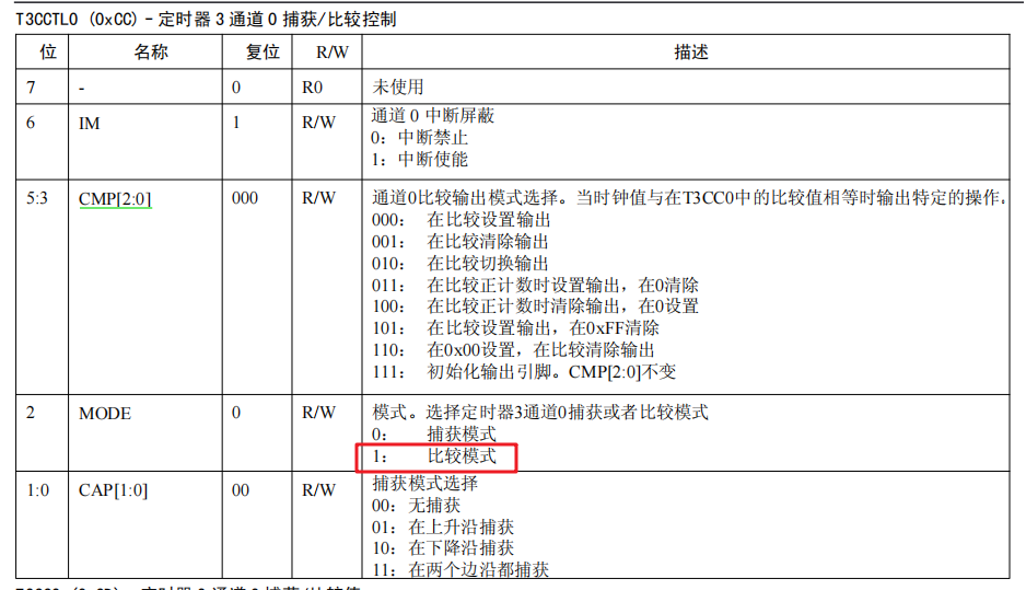
-
T3CC0[SFR(0xCD)]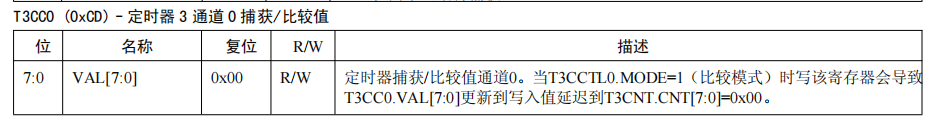
4) Calculation of Counting Value T3CC0
Taking the 1ms timer in this example, with a crystal frequency of 16MHz and a prescaler of 128. The frequency after division: f1 = 16MHz / 128, the period after division: t = 1 / f1, and how many cycles are needed for 1ms after division: T = 1 / (t / 1000) leading to T = 125, which is the value to set for the register T3CC0.
Note: If you want to directly time 1s, an 8-bit register cannot achieve this.
2. Source Code
1. Function
Using the timer to achieve the effect of a breathing light.
2. Effect Picture:
To meet the 10M upload requirement of the article, the frame rate set during the video to gif conversion was relatively low, so you can see a significant brightness change effect; the original mp4 is actually very smooth.
3. Source Code:
#include "iocc2530.h" // Import CC2530 header file
#include "stdio.h"
#include "string.h"

int count = 0;
int pwmT = 0;
int increasing = 1;
int increasingPwm = 1;
#pragma vector = T3_VECTOR
__interrupt void T3_ISR(void)
{
  if(count > pwmT){
    P1_0 = 0;
  }else{
    P1_0 = 1;
  }

  ++count;
  if(count > 1000){     // 1000ms as one cycle
    if(increasingPwm){  // New cycle, new duty cycle
      pwmT += 10;
    }else{
      pwmT -= 10;
    }
    count = 0;
  }

  if(pwmT >= 1050){ // When it reaches the dimmest, set to start brightening flag; here slightly higher than 1000 to make the off effect more obvious
    increasingPwm = 0;
  }

  if(pwmT < 0){    // When it reaches the brightest, set to start dimming flag
    increasingPwm = 1;
  }
}

void initTimer3(){
  T3IE = 1;                     // Enable T3 interrupt
  T3CCTL0 |= 0x04;             // Set T3 mode to compare mode
  T3CC0 = 125;                 // T3 reload value 125
  T3CTL |= 0x02;                 // T3 modulo mode
  EA = 1;                       // Enable global interrupt
  T3CTL |= 0x10;                // Start timer
}

void initLed(){
  P1SEL = 0xfe;    // Set P1.0 as normal I/O
  P1DIR |= 0x01;    // Set P1.0 as output direction
}


int main( void )
{
   initLed();    // Initialize LED port
  initTimer3();  // Initialize interrupt
  while(1){     // Loop waiting for key interrupt to occur
  }
}