Transformation and Application of ZigBee-Based Sensor Experiment Platform
Authors: Ye Yangting, Wang Li (Jianghan University, School of Physics and Information Engineering, Wuhan, Hubei 430056)
Abstract
To address the issues of single functionality and poor mobility of sensor experimental equipment, this paper analyzes the structural characteristics of the sensor and detection technology experimental platform at Jianghan University and designs a sensor experimental platform based on ZigBee technology. This experimental platform improves upon the existing sensor experimental platform by adding ZigBee wireless communication capabilities, thus meeting the experimental teaching needs of both sensor technology and wireless sensor networks courses. The system consists of a sensor experimental template, ZigBee terminal nodes, ZigBee aggregation nodes, and a PC. Each terminal node connects to different sensor templates, transmitting the collected data to the aggregation node via ZigBee wireless network, and ultimately to the PC for observation. After introducing the software and hardware design of the experimental platform, the paper details how to conduct experimental projects using the ZigBee-based wireless strain sensor experiment as an example. The results demonstrate that the data transmission of this experimental platform is reliable and meets the needs of experimental teaching.
Keywords
ZigBee; Sensor; Experimental Platform
0 Introduction
Traditional sensor and detection technology experiments generally collect and monitor sensor data through wired methods. Although this can meet the requirements of sensor experiment courses, this detection method lacks flexibility and cannot perform long-distance measurements[1]. Applying this wired detection technology in harsh environmental engineering applications can lead to practical issues such as difficulty in wiring sensor devices and high costs. Therefore, this paper considers the advantages of wireless sensor networks, such as strong mobility and high reliability, and improves upon the existing sensor and detection technology experimental platform, retaining the original sensor performance testing functions while adding a ZigBee wireless communication module to design a ZigBee-based wireless sensor network experimental platform. This platform meets the experimental teaching needs of both sensor technology and wireless sensor networks, providing students with a comprehensive experimental teaching platform.
1 Overall Design Plan of the Experimental Platform
In 2004, Jianghan University purchased the CSY3000 sensor and detection technology experimental platform produced by Zhejiang Gaolian Company. This experimental platform consists of a main control console (including signal sources, instruments, vibration sources, etc.), sensors, and corresponding sensor experimental templates. The experimental templates include 18 types of sensors such as resistive strain sensors, differential transformers, piezoelectric sensors, optical displacement sensors, and temperature sensors[2].
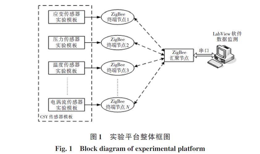
This paper presents the improvement method for the sensor experimental platform as shown in Figure 1, which adds multiple ZigBee terminal collection nodes and one ZigBee aggregation node to the existing system, forming a ZigBee-based wireless sensor network data acquisition system with CSY sensor experimental templates and a PC. The working principle of this system is that each terminal node connects to different sensor templates, and through multi-hop forwarding, the collected data is transmitted to the aggregation node via the wireless network. The aggregation node manages, classifies, and processes the data, and then transmits it to the PC via a serial port. The PC uses upper computer software to observe the data in real time[3] and performs relevant calculations to obtain performance parameters such as sensor sensitivity and non-linearity errors. This system consists of one aggregation node corresponding to multiple terminal nodes, forming a star network topology. After powering on the aggregation node, the network is established, and each sensor experimental template joins the network after powering on the ZigBee terminal node, with the aggregation node assigning network addresses to each terminal node.
2 Hardware Design of the Experimental Platform
2.1 Design of Wireless Sensor Aggregation Node
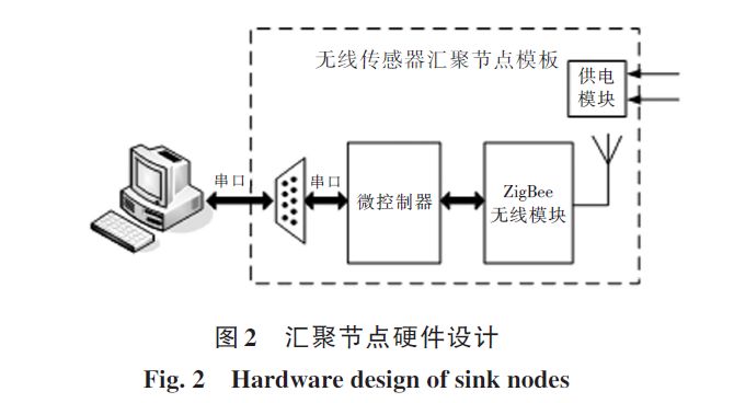
As shown in Figure 2, the aggregation node template includes a ZigBee wireless communication module, a microcontroller, and a power supply module. The ZigBee wireless communication module uses the CC2530 chip produced by TI as the main controller. The aggregation node template serves as the coordinator of the ZigBee network, summarizing and analyzing data from the entire area, establishing the network, and waiting for the joining of terminal nodes or routers[4]. Considering that the aggregation node needs to analyze and process data received from each wireless sensor terminal node and communicate with the PC, a microcontroller is added to enhance the data processing speed and transmission rate. Here, the 32-bit microcontroller STM32F103VET6 is selected, which is based on the Cortex-M3 core and has a working frequency of up to 72 MHz. Its rich peripherals include three USART interfaces, meeting the communication needs with both the ZigBee wireless module and the PC[5].
2.2 Design of Wireless Sensor Terminal Node
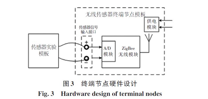
The ZigBee terminal node is an important part of the wireless sensor network, connecting various sensor templates and transmitting the collected data to the aggregation node via multi-hop. The wireless sensor terminal node template mainly consists of the ZigBee wireless communication module and its power supply module, with the ZigBee communication module also using the CC2530 from TI as the main controller. The CC2530 integrates a 12-bit resolution ADC module[6], meeting the high-precision measurement needs of various sensors. During the experiment, the output signal of the sensor template can be connected to the ADC interface of the CC2530 via wires, as shown in Figure 3. The power supply module can either use the power supply on the experimental platform or choose battery power, facilitating the mobility of the device.
3 Software Design of the Experimental Platform
This paper utilizes the Z-Stack protocol stack provided by TI for software development on the CC2530, allowing users to directly use the API provided by the protocol stack for application development without concern for the specific implementation of the ZigBee protocol, thus improving development efficiency[7].
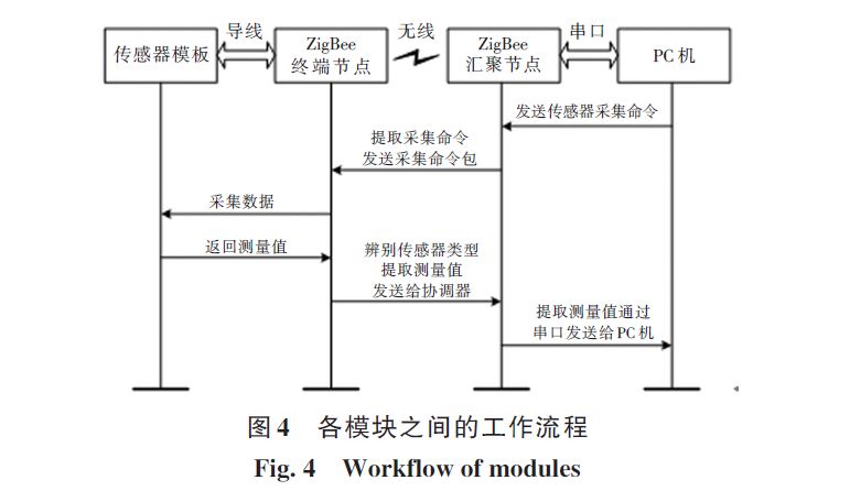
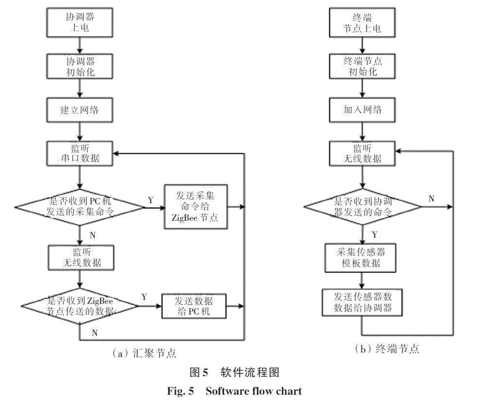
The software design of this experimental platform mainly includes the software design of the wireless sensor terminal nodes and the aggregation node. The primary task of the wireless sensor terminal node is to listen for collection commands sent from the PC via the ZigBee wireless network and collect data from the sensor template, ultimately sending it to the aggregation node via ZigBee network. The terminal node adopts a timed collection method with an interval of 5 seconds, storing the collected data in memory for management. The main tasks of the aggregation node include two parts: one is to listen for collection commands issued by the PC via the serial port; the other is to listen for sensor measurement data transmitted from various terminal collection nodes in the wireless network, and then transmit the data to the PC via the serial port, where the PC processes and analyzes the data using upper computer software. The workflow among the PC, ZigBee aggregation node, and terminal collection nodes is shown in Figure 4, while the software flowcharts for the aggregation node and terminal nodes are shown in Figure 5.
4 ZigBee-Based Wireless Resistive Strain Sensor Experiment
Typical sensor experiment projects include strain sensors, differential transformers, capacitive sensors, eddy current sensors, and more than ten types of sensor experiments. Although the CSY sensor experimental platform allows students to comprehensively master the use of various sensors, most experiments are single-verification types. Below, the wireless resistive strain sensor experiment will be used as an example to detail how to conduct comprehensive experimental projects using the ZigBee-based wireless sensor experimental platform.
4.1 Principle of Wireless Resistive Strain Sensor Experiment
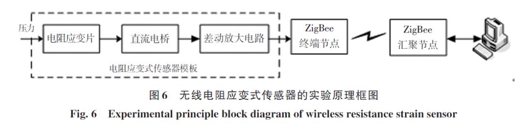
The basic principle of the resistive strain sensor experiment is that the resistive strain gauge is attached to the surface of the test piece, producing mechanical deformation under external force, which causes a change in resistance. This change in resistance is then converted into a change in voltage via a measurement bridge[8], amplified by a differential amplifier circuit for small signals, and finally transmitted to a remote PC for observation via the ZigBee wireless network. The experimental principle block diagram of the wireless resistive strain sensor is shown in Figure 6.
4.2 Experimental Process
4.2.1 Devices and Templates: Resistive strain sensor experimental template, wireless sensor terminal node template, wireless sensor aggregation node template, weights, voltmeter, ±15 V power supply, ±4 V power supply, 5 V power supply, multimeter, and PC.
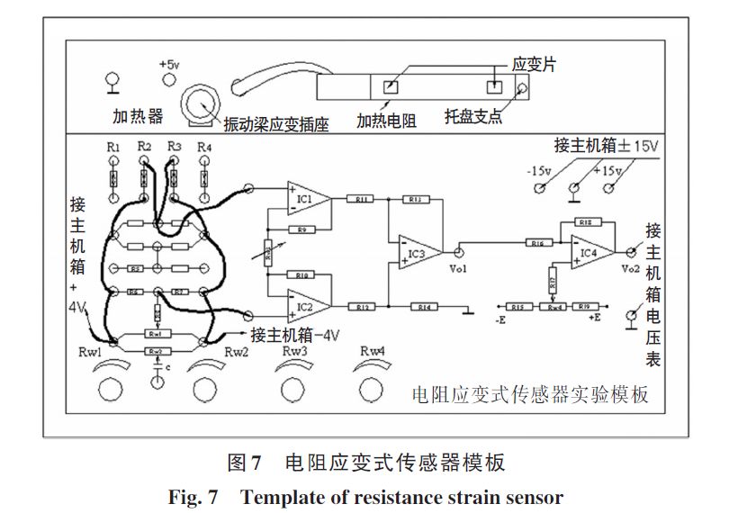
4.2.2 Resistive Strain Sensor Template: Figure 7 shows the CSY strain sensor template. The experimental template includes R1, R2, R3, and R4 as strain gauges, which can be configured in different connection methods to perform single-arm bridge, half-bridge differential bridge, and full-bridge differential bridge performance testing experiments[9]. The output voltage signal of this bridge circuit is first amplified by a differential amplifier circuit composed of three operational amplifiers with high common-mode rejection ratio, and then connected to an inverting amplifier circuit for secondary amplification, outputting suitable voltage for the voltmeter to read or for the ZigBee terminal node to collect.
4.2.3 Experimental Steps: 1) Zero adjustment of the differential amplifier circuit: Connect the resistive strain sensor experimental template to the ±15 V power supply (from the main control console), and ground both input terminals of the differential amplifier. Adjust Rw4 to zero the differential amplifier circuit.
2) Connect the ZigBee wireless template: Power the aggregation node sensor module with a 5 V power supply, then connect the input terminal of the terminal node to the output terminal of the strain sensor template. Finally, power on the terminal collection node to ensure successful networking between the aggregation node and the terminal collection node.
3) Connect the bridge circuit: As shown in Figure 7, connect the resistive strain gauges R2 and R3 on the strain sensor template to form a half-bridge circuit. Rw1 is the bridge balance potentiometer. Connect the output terminal of the bridge to the input terminal of the differential amplifier circuit, and connect the bridge power supply of ±4 V, adjusting Rw1 to display zero on the voltmeter.
4) Performance testing of the strain half-bridge: Place a weight on the tray of the strain sensor, read the voltmeter value, sequentially increase the weights (20 g each) and read the corresponding digital display values, while also observing the corresponding values on the PC software.
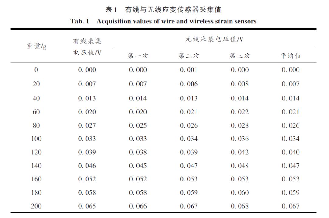
4.2.4 Measurement Results: To verify the accuracy of the data collected by the ZigBee wireless strain sensor, a comparison is made between the voltage values collected via wired methods and the average voltage values collected wirelessly. The test results are shown in Table 1, with both results being essentially the same, meeting practical engineering needs.
5 Conclusion
This paper combines wireless sensor network technology to improve the existing sensor experimental platform, designing a ZigBee-based comprehensive sensor experimental platform that saves educational costs while meeting the experimental teaching needs of multiple courses, including sensor and detection technology and wireless sensor networks, thereby improving teaching effectiveness. Using the wireless resistive strain sensor experiment as an example, this paper demonstrates that the platform has good networking effects, high data transmission accuracy, and meets the needs of experimental teaching. The platform has characteristics such as modularity and openness, allowing students to select different sensor modules to build various wireless sensor network systems, suitable for applications in smart homes, smart transportation, smart grids, and other IoT fields[10], with broad application prospects.
References: Ye Yangting, Wang Li. Transformation and Application of ZigBee-Based Sensor Experiment Platform [J]. Journal of Jianghan University (Natural Science Edition), 2018, 46(1): 36-41.
DOI: 10.16389/j.cnki.cn42-1737/n.2018.01.007