Keywords: .extSettings, file structure, BSP
Directory Preview
1. Introduction
2. The Role of .extSetting File
3. Usage Example
4. Summary
01Introduction
While reading the UM1718 document, I found that CubeMX has a great feature that allows you to use the “.extSettings” file once, so that no matter which IDE you use later (as long as it is supported by CubeMX), you do not need to manually configure the file structure or include header file paths again. This feature helps maintain consistency in the configurations across various IDEs (only those supported by CubeMX) and reduces workload. Some customers have also inquired about how to add project files, so this article introduces this feature.
02
The Role of .extSettings File
The “.extSettings” file is a supplement to the CubeMX configuration; it provides additional configuration based on the CubeMX settings and does not replace them. This point is important to note.
Overall, the configurations in the “.extSettings” file consist of three parts: [ProjectFiles], [Groups], and [Others]. Below is an introduction to the functions of these three parts.
2.1. [ProjectFiles]
The [ProjectFiles] section is mainly used to include some directories, such as the directory where header files are stored.
Syntax: HeaderPath=<include directory 1 path>;<include directory 2 path>
Example: HeaderPath=../BSP/STM32H735G-DK
Note: The paths here are relative to the “*.cproject” or “*.project” file (if the generated code is for CubeIDE). If the generated code is for another IDE, then this path is relative to that project file, such as the “*.eww” file (IAR) or “*.uvprojx” file (KEIL).
Effect: By adding the content from the example in the “.extSettings” file and regenerating the code, the result is shown in Figure 1, where the red box indicates the directories included through the “.extSettings” file, which can be seen included in the project.

Figure 1: Directories included in the CubeIDE project after configuring [ProjectFiles]
2.2. [Groups]
This section is mainly used to create file groups in the project and add files to these groups to organize the project’s file structure.
Syntax: <Group name>=<file pathname1>;<file pathname2>
Example: Drivers/BSP/STM32H735G-DK=../BSP/STM32H735G-DK/stm32h735g_discovery.c;
Note: <Group name> is the name of the file group in the project (if it does not exist, it will be created automatically); <file pathname> is the file path. The statement in the example creates a nested file group “Drivers/BSP/STM32H735G-DK” (which can be nested multiple levels) and adds the “stm32h735g_discovery.c” file to this group. Multiple files can be added to a file group as long as they are separated by semicolons (“;”).
Effect: By adding the content from the example in the “.extSettings” file and regenerating the code, the result is shown in Figure 2.
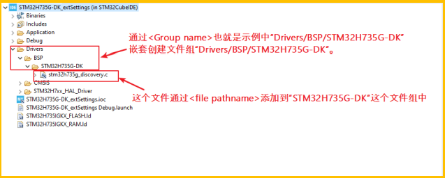
Figure 2: Project file structure after configuring [Groups] in CubeIDE
2.3. [Others]
The [Others] section is mainly used to enable some HAL templates and add some preprocessor definition statements.
2.3.1. Adding HAL Templates
Syntax: HALModule=<ModuleName1>;<ModuleName2>;
Example: HALModule=SPI;ADC;
Effect: By adding the content from the example in the “.extSettings” file and regenerating the code, if the project is created using H7 series chips, the “stm32h7xx_hal_conf.h” file (if using other series chips, the name will differ slightly) will automatically include the macros “HAL_SPI_MODULE_ENABLED” and “HAL_ADC_MODULE_ENABLED”, which are used to include the header files for SPI and ADC. As shown in Figure 3:
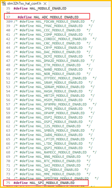
Figure 3: Automatically added content in HAL configuration file after configuring [Other] for HALModule
2.3.2. Adding Preprocessor Definition Statements
Syntax: Define=<define1_name>;<define2_name>
Example: Define=TEST_STM32H735G_DEMO
Effect: By adding the content from the example in the “.extSettings” file and regenerating the code, you can see that the preprocessor definitions configured in the “.extSettings” file have been added to the project.
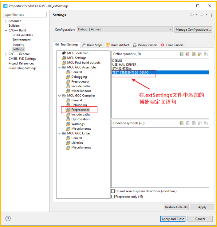
Figure 4: Automatically added preprocessor statements in the project after configuring [Other] for Define
03Usage Example
The following example is based on the STM32H735G-DK board, using the BSP drivers from “STM32Cube_FW_H7_V1.10.0”. The goal is to make the LED1 on the board toggle its state every 0.5 seconds. Below are the steps to achieve this:
3.1.1. Create CubeMX Configuration File
Create a project for STM32H735IGK6 (STM32H735G-DK) using STM32CubeMX, keeping all other configurations at their default values, and save this configuration file. As shown in Figure 5:
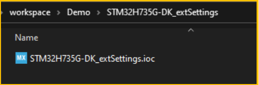
Figure 5: Saving the configuration file generated by CubeMX
3.1.2. Add BSP Files
Copy the “BSP” directory and its files from the “STM32Cube_FW_H7_V1.10.0/Drivers” path to the project directory (this is copied to the same directory as the .ioc file, but you can also copy it elsewhere as long as it is included in the “.extSettings” file). As shown in Figure 6:
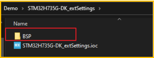
Figure 6: Copying “BSP” to the project directory
Rename the file “stm32h735g_discovery_conf_template.h” in the BSP to “stm32h735g_discovery_conf.h”
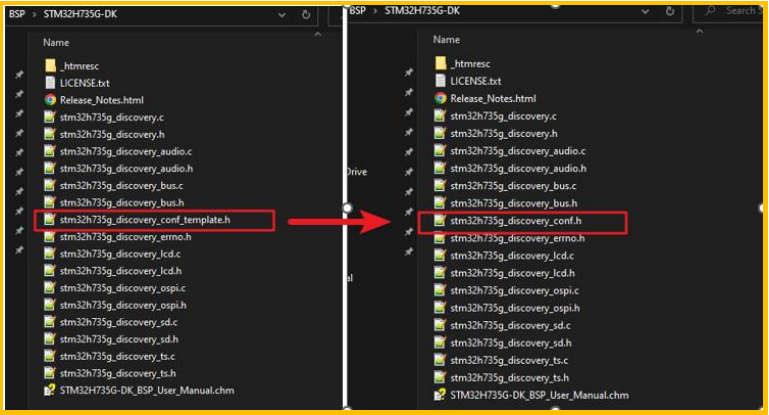
Figure 7: Adding the configuration file of BSP
3.1.3. Create .extSettings File
Create a “.extSettings” file in the same directory as the .ioc file. As shown in Figure 8:
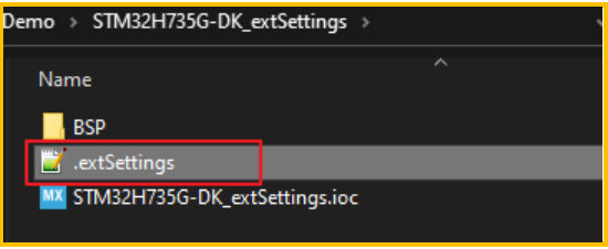
Figure 8: Adding the .extSettings file
Note: The .extSettings file must be placed in the same directory as the .ioc file.
3.1.4. Modify the Content of the .extSettings File
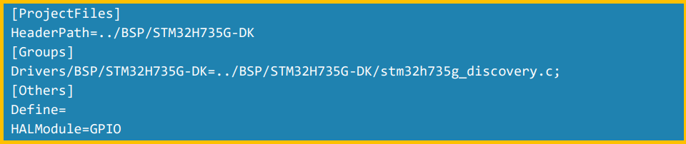
(1) Since GPIO operations are needed, and the BSP files are based on the HAL library, the HAL library for GPIO needs to be used (to avoid the GPIO module not being enabled, we enable the GPIO module here). The content to be added in the [Others] section is: HALModule=GPIO
(2) Add the directories that need to be included from the BSP. Thus, the content to be added in the [ProjectFiles] section is: HeaderPath=../BSP/STM32H735G-DK
(3) Add the files from the BSP to the project. Since only the LED needs to be operated, we only need to add the “stm32h735g_discovery.c” file and create the file group “STM32H735G-DK”. Therefore, the content to be added in the [Groups] section is: Drivers/BSP/STM32H735G-DK=../BSP/STM32H735G-DK/stm32h735g_discovery.c;
In summary, the content to be added in the .extSettings file is:
3.1.5. Use CubeMX to Generate Project Code for Different IDEs
Use CubeMX to generate code (GENERATE CODE), generating project codes for CubeIDE, IAR, and KEIL.
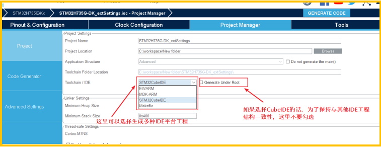
Figure 9: Using CubeMX to generate code
After generating the code, the project files structure for different IDEs is as shown below:
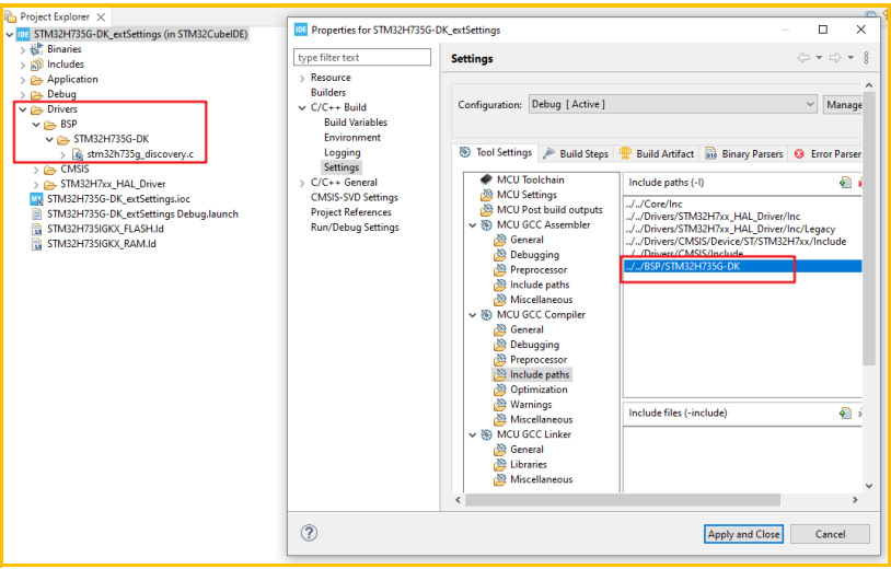
Figure 10: STM32CubeIDE
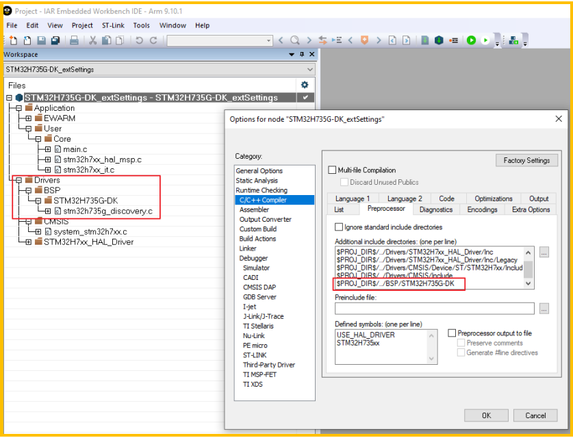
Figure 11: IAR
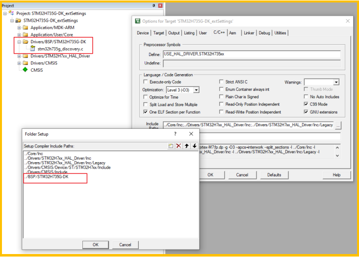
Figure 12: KEIL
As can be seen from the above figures, the “stm32h735g_discovery.c” file has been added to the project, and the BSP directory has also been included in the project.
3.1.6. Add Code to Implement Functionality
1. Include the “stm32h735g_discovery.h” header file.

Figure 13: Including “stm32h735g_discovery.h”
2. Use BSP to initialize the configuration for LED1.
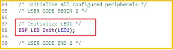
Figure 14: Using BSP to initialize the configuration for LED1
3. Add the operation to toggle LED1.
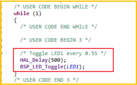
Figure 15: Adding the toggle operation for LED
Result: After compiling and downloading using these three IDEs, the operation of LED1 toggling its state every 0.5 seconds can be achieved.
04Summary
Using the “.extSettings” file to configure the project’s file structure allows for one-time configuration that is usable across multiple platforms and maintains consistency in configurations.
Note: The “.extSettings” file must be placed in the same directory as the .ioc file.
For the complete content, please click “Read Original” to download the original document.
 Subscription Account
Follow STM32
 Video Account
 B Station Account
▽Click “Read Original” to download the original document