In the development of ECU (Electronic Control Unit) software, conditional judgment is key to implementing various control logics. SIMULINK, as a powerful graphical modeling tool, provides a rich set of functional modules for ECU application layer software development, among which the if-else structure is one of the commonly used methods for implementing conditional control. By properly utilizing the if-else module, it is possible to execute different operations based on different conditions, meeting the precise control requirements of ECU software for complex operating conditions.
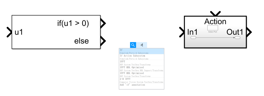
Therefore, this article will mainly introduce the usage of if-else in SIMULINK’s ECU application layer software modeling, detailing the addition, configuration, and application of the if-else module through specific examples, showcasing its important role in implementing conditional judgments and different path selections.
1 Introduction to the if-else Module
In SIMULINK, the if-else module is primarily used to implement conditional judgment functions. It determines which branch path to execute by judging whether the input signal meets specific conditions. The if-else module is usually used in conjunction with the If Action Subsystem module to form a complete conditional judgment logic structure, controlling the model behavior under different conditions.
Of course, in cases where the judgment logic is not complex, the most commonly used is the Switch module, which means if the condition is met, it follows the upper branch; otherwise, it follows the lower branch.
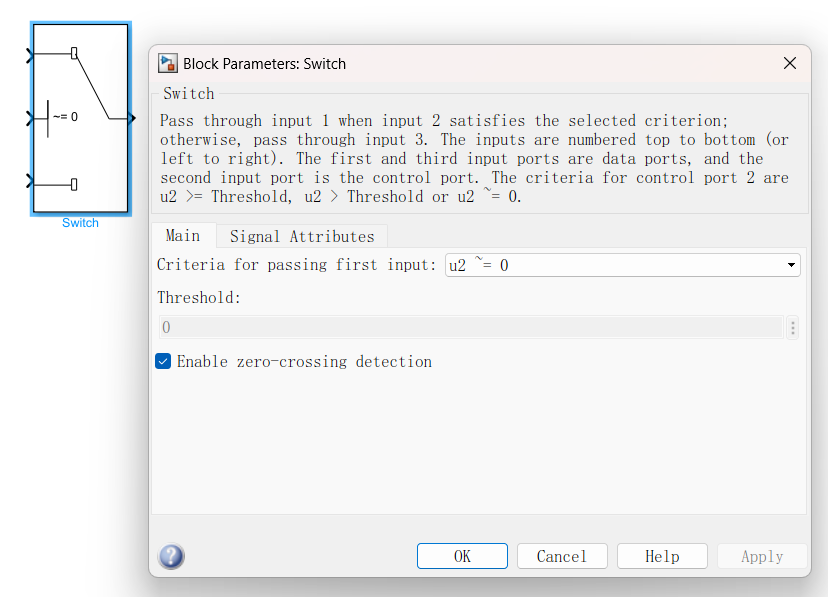
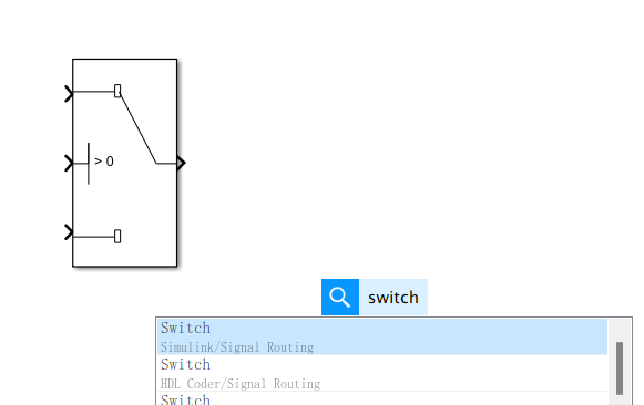 For the use of Switch, it is recommended to set the judgment condition to not equal to 0, especially for a software development team, to avoid bugs caused by different modeling styles.
 In cases where the judgment logic is complex, using the if-else module will be more reasonable, so we will focus next on the addition and configuration of the if-else module.
-
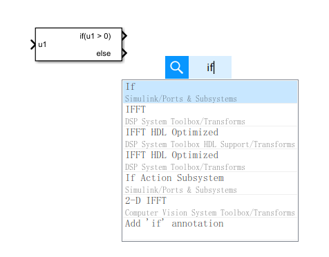
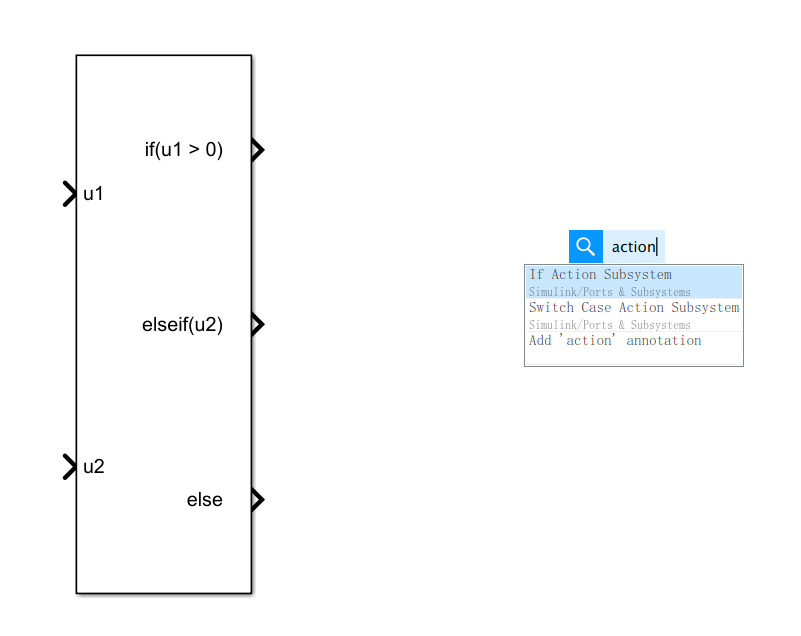
Adding the if module: Open the SIMULINK editing panel, double-click in a blank area, type “if”, and select the If module from the search results to add it to the model.
-
Adding the If Action Subsystem module: Similarly, double-click in a blank area, type “if”, and select the If Action Subsystem module to add it to the model. This module is a subsystem that executes corresponding actions when the condition is met.
-
Configuring the if module parameters:
-
Number of inputs: Set the number of input ports based on the actual conditional judgment needs.
-
If expression: Input the judgment condition expression, such as “u1>5” which indicates judging whether the input signal u1 is greater than 5.
-
Elseif expressions: If there are multiple judgment conditions, you can continue to add them in this option, separated by commas.
-
Show else condition: Check this option to display the output signal of the else branch for connecting the corresponding subsystem in the model.
Double-click the if module to configure the parameters in the pop-up property box:
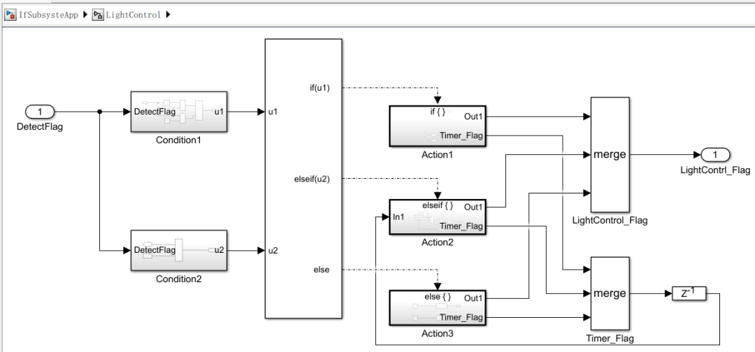
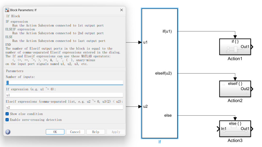 For the configuration of the if module parameters, I personally prefer to input only true or false conditions for the if and elseif branches, without doing additional relational or logical operations in the judgment conditions. Therefore, the software architecture adopted is as follows:
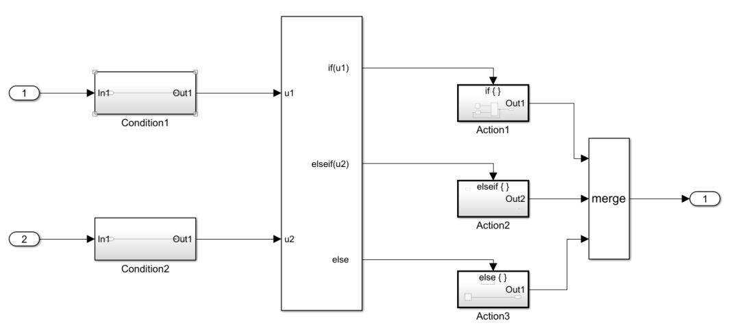 That is: Judgment condition subsystem — if module — action subsystem.For the input of the if module, each judgment branch creates a corresponding judgment condition subsystem, whose output results can only be true or false; for the output of the if module, each judgment branch’s action creates a corresponding Action subsystem, outputting the final result through the Merge module.I believe this architecture logic is very clear; conditions are conditions, actions are actions, and when comparing requirements or troubleshooting issues, one can quickly focus on the target module.2 Application of the if-else Module
Next, let’s take an example to gain a deeper understanding of the specific application of the if-else module in ECU application layer software modeling.
Assuming we need to create a model for controlling an induction light with the following requirements:
-
The light remains on when someone is present.
-
The light turns on 2 seconds after someone enters.
-
The light does not turn on when no one passes by.
For this requirement, we design the model logic as follows:
Connect the output of the If module to three If Action Subsystem modules, one for handling the logic when the condition of “someone enters” is met, one for handling the logic when the condition of “someone stays”, and one for handling the logic of “no one enters”.
-
In the “someone enters” subsystem, add a timing trigger logic judgment to control the light to remain off.
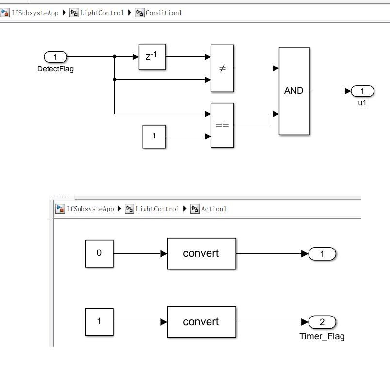
-
When someone is detected entering, and the timing trigger flag is activated, start timing; after 2 seconds, output a signal to control the light to turn on.
-
In the “no one enters” subsystem, no additional modules are needed; simply keep the light off.
The final constructed model is shown below:
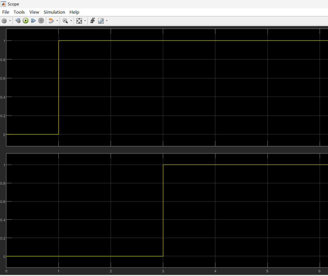
Finally, we will simulate whether this model meets the requirements. Initially, it is in a state of no one entering for 1 second, then switches to someone entering and stays. As shown in the figure below. From the figure, it can be seen that after detecting someone entering at 1 second, timing for 2 seconds, at 3 seconds, the light starts to be controlled to turn on and remains on. This simply verifies the degree of requirement fulfillment.
This is a simple example illustrating the use of the if-else module. In automotive ECU application models, this module is used extremely frequently. It is important to adopt a reasonable software architecture, that is, first build the framework, and then construct detailed control logic based on requirements.
3 Conclusion
In SIMULINK’s ECU application layer software modeling, the if-else module is an important tool for implementing conditional judgments and path selections. By properly utilizing the if-else module, complex control logic can be constructed clearly and intuitively, meeting the precise control requirements of ECU software for different operating conditions. It is important to note:
- When building the model, ensure that the connections between the if module and the If Action Subsystem module are correct to avoid signal flow errors that could lead to logical confusion.
-
When writing conditional expressions, ensure they accurately reflect the actual control requirements to avoid logical errors due to improper condition settings.
-
In some complex control logics, it may be necessary to use nested if-else modules. In this case, pay attention to the hierarchy of the modules and the signal transmission relationships to ensure the model’s readability and maintainability.
In practical applications, it is essential to fully understand the functions and configuration methods of the if-else module, paying attention to detail issues during the model building process to ensure the correctness and reliability of the model. At the same time, combining simulation verification and code generation functions can further improve the efficiency and quality of ECU software development.
Creating content is not easy, please like, save, and follow!!
Automotive R&D group chat, interested friends please add the group owner: prOmiseyes, with a note: company + position to join the group. Limited to automotive industry personnel.
Series of articles on ECU application layer software models are continuously updated, teaching you application layer development from scratch:
- Example 1 of building ECU application layer software model (qq.com)
- How to automatically generate code for ECU application layer software model 2 (qq.com)
- How to run ECU application layer software periodically 3 (qq.com)
- Code generation configuration related to ECU application layer software model 4 (qq.com)
- Data dictionary DD in ECU application layer software model 5 (qq.com)
- Data dictionary storage classes in ECU application layer software model 6 (qq.com)
- Fixed-point implementation in ECU application layer software model 7 (qq.com)
- 5 methods of fixed-point implementation in ECU application software model 8 (qq.com)
- Custom storage classes in ECU application layer software model 9 (qq.com)
- Summary of model generation code in ECU application layer software model 10 (qq.com)
- CAN reception in ECU application layer software model 11 (qq.com)
- Data stream reception of CAN messages in ECU application layer software model 12
- How to leverage AI in ECU software development? Application of Kimi in MBD development environment 13
-
Detailed explanation of unit test coverage CC, DC, and MCDC in ECU application layer software model 14
-
Application and Principles of Calibration and Observed Quantities in ECU Application Layer Model Development 15
-
Using for loops in ECU application layer model development 16