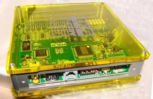
The ECU is the control center of the ABS system, essentially a micro digital computer, typically composed of two microprocessors and other necessary circuits, forming an indivisible unit that cannot be repaired. The basic input signals for the electronic control unit are the wheel speed signals sent from the four wheel sensors, while the output signals include: control signals for the hydraulic control unit, output self-diagnostic signals, and signals for the ABS fault indicator light.

1. ECU’s Anti-lock Control Function
The electronic control unit has the capability to continuously monitor the speed signals from the four wheel sensors. It continuously detects the pulse electrical signals from all four wheel sensors, processes them, and converts them into values proportional to the wheel speed. From these values, the electronic control unit can distinguish which wheel is moving faster and which is slower. The electronic control unit implements anti-lock braking control based on the speeds of the four wheels. Using the data from the wheel sensors as a control basis, once it determines that a wheel is about to lock up, it immediately enters anti-lock control mode, outputting a pulse control voltage of 12V to the hydraulic regulator, controlling the opening and closing of the oil circuit to the wheel cylinder. The change in oil pressure at the wheel cylinder adjusts the braking force on the wheel, preventing it from locking up due to excessive braking force (the frequency of opening and closing generally ranges from 3 to 12 times per second).
In general, the anti-lock control adopts a three-channel approach, meaning that the front wheels have two separate oil circuits for control, allowing the electronic control unit to perform anti-lock braking control for the left and right front wheels independently, while the rear wheels only have one oil circuit. The electronic control unit can only perform centralized control on the two rear wheels (if one rear wheel is about to lock up, the electronic control unit will simultaneously apply anti-lock control to both rear wheels).
2. ECU’s Fault Protection Control Function
The ABS system’s electronic control unit has a fault protection control function. If a fault occurs in the system or it is temporarily disturbed, the electronic control unit will automatically shut down the ABS system, allowing the normal braking system to continue operating.
First, the electronic control unit can monitor its own operation. Since there are two microprocessors in the electronic control unit, they simultaneously receive and process the same input signals and compare them with relevant internal signals and generated external signals in the system to check for consistency, thus calibrating the electronic control unit itself. This calibration is continuous, and if they cannot synchronize, it indicates a problem with the electronic control unit, which will automatically stop the anti-lock braking process and allow the normal braking system to function as usual. At this point, maintenance personnel must inspect the ABS system (including the electronic control unit) to identify the fault.
The input signals from the wheel speed sensors are simultaneously sent to the two microprocessors in the electronic control unit, processed in their logic modules, and output internal signals (wheel speed signals) and external signals (to the hydraulic regulator). Then, these two types of signals are compared and calibrated. The internal signals generated by the logic module are sent to two different comparators (one for each processor), where they are compared. If they do not match, the electronic control unit will stop working. One output from the microprocessor is sent directly to the comparator, while the other is routed through the hydraulic regulator control circuit via a feedback loop to the comparator. If the external signals cannot synchronize through the comparator, the ABS system’s electronic control unit will shut down the anti-lock braking system.
The ABS system’s electronic control unit not only monitors its own internal processes but also supervises the operation of other components in the ABS system. It can programmatically send pulse check signals to the hydraulic regulator’s circuit system and solenoid valves, completing functionality checks without any mechanical action. During the operation of the ABS system, the electronic control unit can also monitor and determine whether the wheel speed signals sent by the sensors are normal.
If a fault occurs in the ABS system, such as brake fluid loss, reduced hydraulic pressure, or loss of wheel speed signals, the electronic control unit will automatically issue commands to allow the normal braking system to operate while stopping the ABS system. If a wheel speed sensor is damaged and outputs a signal, as long as it is within an acceptable limit range, or if strong radio frequency interference causes the sensor to output signals beyond limits, the electronic control unit may decide to either stop the ABS system or allow it to continue functioning based on the situation.
It is important to emphasize that if the amber (yellow) ABS system fault indicator light is illuminated, it indicates that the electronic control unit has stopped the operation of the ABS system or detected a fault in the system. The driver or user must perform maintenance, and if unable to resolve the issue, should promptly take it to a repair shop.