When we submit PCB production data for prototyping, there is an option regarding the Tg value of the material on the online prototyping pricing page of the board factory. Different Tg values will affect the final prototyping costs, which means you have to pay for the Tg value of the material. So, what is this Tg value, and under what circumstances do you need to pay extra for high Tg materials?
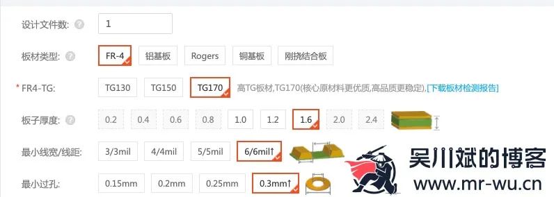
For a long time, the Tg value has been the most common indicator used to classify the grade of FR-4 substrates in the industry. It is generally believed that the higher the Tg value, the higher the reliability of the material.
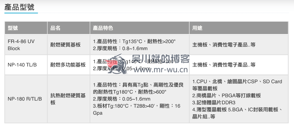
For example, the following image shows the specifications of FR-4 materials captured by Lao Wu in South Asia:
Tg 135℃, Material Use: Motherboards, Consumer Electronics, etc.
Tg 180℃, Material Use: CPU motherboards, DDR3 memory substrates, IC packaging substrates, etc.
The substrate is as important to printed circuit boards as printed circuit boards are to electronic devices. According to the properties of PCB substrates, they can be divided into two major systems: Organic Substrates and Inorganic Substrates.
Organic Substrates consist of layers of multilayer paper impregnated with phenolic resin or layers of non-woven fabric or glass cloth impregnated with epoxy resin, polyimide, cyanate ester, BT resin, etc. The use of these substrates depends on the physical properties required for PCB applications, such as operating temperature, frequency, or mechanical strength.
Inorganic Substrates mainly include ceramic and metal materials, such as aluminum, soft iron, and copper. The use of these substrates usually depends on heat dissipation requirements.
The rigid printed circuit board substrates we commonly use belong to organic substrates, such as FR-4 epoxy glass cloth substrates, which are a type of substrate using epoxy resin as an adhesive and electronic-grade glass fiber cloth as a reinforcing material.
We see that FR-4 uses epoxy resin as an adhesive, and the resin material has an important characteristic parameter: Glass Transition Temperature Tg, which refers to the temperature transition point at which the material changes from a relatively rigid or “glass” state to a pliable or softened state.
The glassy material can reversibly transform between the glassy state and the rubbery state. What does this mean? It means that if the temperature of the adhesive epoxy resin in the FR-4 substrate is below Tg, the material is in a hard “glassy state”. When the temperature exceeds Tg, the material exhibits soft and flexible properties similar to rubber. Yes! It~ becomes 【soft】~ 
Glassy State
The state of the resin material below the Tg temperature is a hard solid, i.e., the glassy state. Under external force, it undergoes some deformation, but the deformation is reversible, meaning that once the external force is removed, the deformation disappears as well, which is the usage state of most resins.
Rubbery State
When the resin is heated above Tg, the molecular chains in the amorphous state begin to move, and the resin enters the rubbery state. The resin in this state is similar to an elastic body in a rubber state, but still possesses reversible deformation properties.
Note that when the temperature exceeds the Tg value, the material gradually becomes softer, and as long as the resin does not decompose, when the temperature cools back down to below Tg, it can return to its previous rigid state.
However, there is a Td value, known as the thermal decomposition temperature, at which resin materials begin to decompose when heated to a certain high temperature. The chemical bonds within the resin begin to break, accompanied by the release of volatile components, which reduces the amount of resin in the PCB substrate. The Td point refers to the temperature point at which this process begins. Td is usually defined as the decomposition temperature point corresponding to a 5% loss of original mass. However, this 5% is very high for multilayer PCBs.
We know that factors affecting the characteristic impedance of transmission lines on PCBs include line width, spacing between traces and reference planes, dielectric constant of the material, etc. The amount of resin in the substrate has a significant impact on dielectric properties, and the evaporation of resin also affects the control of the spacing between traces and reference planes.
For lead-free soldering processes, this Td value needs to be considered. For example, the temperature range for traditional tin-lead soldering processes is 210~245℃, while the temperature range for lead-free soldering processes is 240~270℃.
The two screenshots below are comparisons of two material parameter sheets downloaded from the Jintao official website by Lao Wu. The left is the conventional FR-4 series material, and the right is the lead-free FR-4 material.
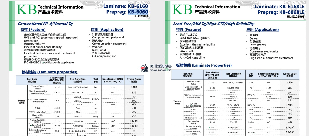
The conventional FR4 material KB-6160 has a Tg value of 135℃, and a Td value of 305℃ for 5% mass loss.
The lead-free FR4 material KB-6168LE has a Tg value of 185℃, and a Td value of 359℃ for 5% mass loss.
We see that the Td values of conventional FR4 materials are all above 300℃, while the temperature range for leaded soldering processes is 240~270℃. Does the Td value fully meet the requirements? Why do we still need a lead-free version?
As Lao Wu mentioned above, the 5% resin mass loss rate is too large for multilayer PCBs that require impedance control. For tin-lead soldering processes, the temperature range of 210~245℃ generally does not cause significant thermal decomposition of the material, while the temperature range of 240~270℃ for lead-free soldering has already begun to lose 1.5~3% of the resin mass. Although this is less than the 5% required by IPC standards, this loss of resin mass cannot be ignored. At the same time, this level of decomposition may affect the long-term reliability of the substrate or lead to defects such as delamination or voids during the soldering process, especially in cases where multiple soldering processes or rework heating occur.
Therefore, if using lead-free soldering processes, in addition to considering the Tg value, Td value must also be a key consideration.
The performance of substrate materials above and below the Tg value differs significantly. However, the Tg value is generally described as a very precise temperature value, such as Tg 135, which does not mean that once the temperature exceeds 135℃, the substrate becomes soft. Instead, when the temperature approaches the Tg value, the material’s properties begin to change, and it is a gradual process.
The Tg value of the resin system affects the material’s performance in two main aspects:
-
Impact of thermal expansion
-
Curing time of the resin system
When the board heats up, imagine the spacing of BGA pads during SMT soldering also changes, right? Moreover, the mechanical stress caused by thermal expansion can create fine cracks in the connections between traces and pads on the PCB. These cracks may not be detected during the final open/short circuit testing after PCB production, but may manifest after secondary heating during SMT, which often leaves people confused. The worst-case scenario is that during SMT heating, no issues appear, but in a usage environment with alternating hot and cold, the thermal expansion of the board causes these fine cracks to occur randomly, leading to equipment failure.
In addition to the standard Tg and Td values, the thermal performance parameters of substrate materials also include Coefficient of Thermal Expansion (CTE), which has CTE values in both X/Y and Z axes.
The Z-axis CTE has a significant impact on the reliability of PCBs. Since plated holes penetrate the PCB in the Z-axis, the thermal expansion and contraction within the substrate can cause distortion and plastic deformation of the plated holes, as well as deformation of the copper pads on the PCB surface.
During SMT, the X/Y axis CTE becomes very important. Especially when using Chip Scale Packages (CSP) and chip-on-board mounting, the importance of CTE is even more pronounced. Additionally, the X/Y axis CTE also affects the adhesion and delamination resistance of copper foil laminate or PCB inner layers. This is particularly important for PCBs using lead-free soldering processes, where the X/Y axis CTE values in each layer become especially critical.
So, is a high Tg value substrate always better? In many discussions about Tg values, it is often assumed that a higher Tg value is always beneficial for the substrate, but this is not always the case. It can be confirmed that for a given resin system, high Tg value substrates begin to expand at a slower rate when heated, and the overall expansion is greatly related to the type of material. Low Tg value substrates may exhibit less overall expansion than high Tg value substrates, mainly due to the CTE value of the resin itself or the addition of inorganic fillers in the resin formulation that reduce the CTE of the substrate.
It is also important to note that some low-end FR-4 materials with a standard Tg value of 140℃ may have a higher thermal decomposition temperature Td than those with a standard Tg value of 170℃. As Lao Wu mentioned above, Td is a very important indicator for lead-free soldering, and it is generally recommended to choose materials with a higher Td value. High-end FR-4 materials often possess both high Tg and high Td values.
Furthermore, high Tg value substrates are often stiffer and more brittle than low Tg value substrates, which can affect the production efficiency of the PCB manufacturing process, especially during drilling operations.
For example, a certain company posted that as the boards become denser, the spacing between vias is getting smaller, leading to higher material requirements. Therefore, this company will provide TG=155 mid-TG materials for multilayer board charging services!
Why the extra charge?
-
The cost of TG=155 materials is about 20% higher than that of TG=135 materials, yes, the incoming materials are more expensive.
-
Because of drilling, mid-TG requires new drill bits for better results (generally, drill bits can be sharpened 4 times), as it is too hard.
-
Pressing time: Ordinary TG=135 only requires 110 minutes of pressing, while mid-TG=155 must be pressed for 150 minutes.
Why provide mid or high Tg materials? The board factory said that one reason is that due to the high density of vias, the spacing of ordinary TG vias cannot be less than 12MIL, while mid-TG cannot be less than 10MIL. Because the substrate has glass cloth, there will be some pulling during drilling, and if you pull a little on both vias, it will create a “lamp wick effect”. Mid-TG, being harder, has different components in the substrate, and using new drill bits can effectively prevent the lamp wick effect. For subsequent high-difficulty multilayer boards, if the spacing between vias is too tight, the company will require customers to choose mid-TG materials for production!
The second reason is that as the Tg of the substrate increases, the thermal resistance, moisture resistance, chemical resistance, and stability of the printed board will all improve. The higher the Tg value, the better the temperature resistance performance of the material, especially in lead-free tin spraying processes, high Tg applications are more common.
This is considered from the manufacturability of the board factory, and if the PCB assembly uses lead-free soldering processes, it is also necessary to comprehensively consider the glass transition temperature Tg, decomposition temperature Td, coefficient of thermal expansion CTE, moisture absorption rate, delamination time, and other factors.