

Author: aurelianliu
Refer to scheduling, memory, files, networks, etc., encountered during work.
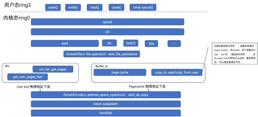
1. OS Running States
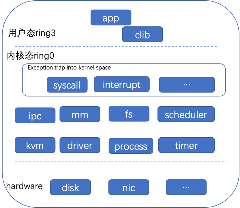
X86 architecture, user mode runs in ring3, kernel mode runs in ring0, two privilege levels.
(1) The kernel and some privileged instructions, such as filling page tables, switching process environments, etc., generally operate in ring0. Kernel mode includes the exception vector table (syscall, interrupts, etc.), memory management, scheduler, file system, network, virtualization, drivers, etc.
(2) In ring3, only part of the registers can be accessed, performing coroutine switching, etc. User programs can run. User mode libraries, services, etc.
(3) User mode crashes can be resolved by restarting the app; the system is safe. Kernel mode crashes require a full system reboot.
(4) Process isolation is achieved through page tables, and memory is generally not visible between processes (except for shared memory). Kernel mode memory is globally visible.
2. Scheduling
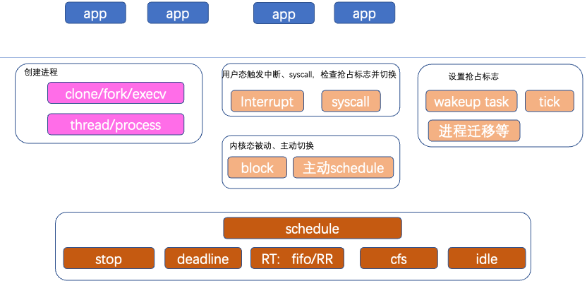
The scheduler consists of scheduling classes (such as cfs, rt, stop, deadline, idle, etc., which are all scheduling classes) and a general scheduling module (mainly in core.c). The scheduler needs support from preemption and switching mechanisms and requires context processes/threads for scheduling.
Processes can be created primarily through clone, fork, execv, etc. Preemption includes setting the preemption flag need_sched and executing preemption. The preemption flag is generally supported by the scheduling classes; for example, when the quota allocated by cfs expires, the preemption flag is set; when a higher-priority process arrives, the preemption flag is set.
Execution of preemption is divided into user mode preemption and kernel mode preemption. Generally, only user mode preemption is enabled; only in scenarios with very high real-time requirements is kernel mode preemption considered. User mode preemption means that while running in user mode, if a syscall, interrupt, or page fault occurs, it enters the kernel and checks if there is a need_sched preemption flag when returning to user mode (entry_64.S); if there is, preemption is executed through schedule() to select the new process to execute. Kernel mode preemption occurs when running in kernel mode and an exception triggers preemption, for example, when an interrupt or tick arrives.
In schedule(), the process context switch is completed, switching from process A to process B, process A->schedule()->process B, saving process A’s register context and restoring process B’s register context to complete the switch.
The scheduling classes are prioritized, including stop (mainly used for inter-core communication, etc.), deadline, RT, cfs, idle, etc.
2.1 CFS
CFS is a Completely Fair Scheduler.
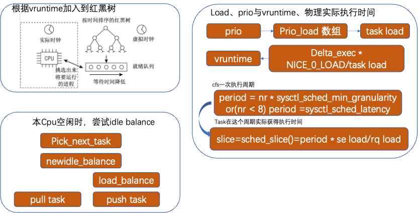
Vruntime. CFS determines the execution order of processes based on virtual clock vruntime, completely fair means that the vruntime of processes running is exactly the same. Vruntime is calculated based on actual execution time delta_exec, NICE_0_LOAD, and task load:
vruntime = delta_exec * NICE_0_LOAD / load
or:
(delta_exec * (NICE_0_LOAD * load->inv_weight)) >> WMULT_SHIFT
Load has process prio calculated through arrays sched_prio_to_weight[] and sched_prio_to_wmult[]. The higher the Nice value or priority, the larger the load value, the same physical execution time results in a smaller vruntime value, thus executing longer in practice; however, from the vruntime perspective, everyone executes the same virtual time. For instance, if process A has a prio of 15 and process B has a prio of 18, they are allocated corresponding weight values of 36 and 18. If both processes execute vruntime for 1024ms, the corresponding actual execution time is delta_exec= (vruntime/ NICE_0_LOAD)*load, process A execution time = (1024/1024)*36=36ms, process B actual execution time (1024/1024)*18=18ms.
Processes vruntime are managed through a red-black tree; the smaller the vruntime value, the closer it is to the left side, indicating that it needs to execute first if there are no higher priority preemptions or queues.
Task’s actual execution time is the slice. A task corresponds to a scheduling entity se in CFS. The current queue processes executing once constitute a period. Each process obtains a slice proportional to the load of this se in relation to the total load of all processes in the overall rq queue, multiplied by the period.
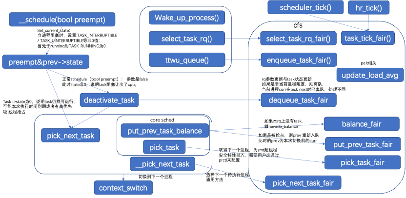
2.2 CFS Operating Mechanism
The first step is to wake up the process. Through wake_up_process/wake_up_new_process, a process is awakened, usually when resources are ready or a waiting lock is released, then waking up the sleeping process.
CPU selection. When waking up a process, it needs to select the most idle or memory-affinity suitable CPU within the process’s CPU affinity range, then add it to this CPU’s run queue rq.
Preemption. After the current process’s slice execution is completed, the clock cycle tick sets the preemption flag and executes preemption at a reasonable time. The process can also voluntarily call schedule() to yield the CPU or yield the CPU while acquiring a lock.
Switching. If the preemption flag is set at the appropriate preemption time or when the process voluntarily yields the CPU, the next process to execute needs to be selected, completing the switch through schedule().
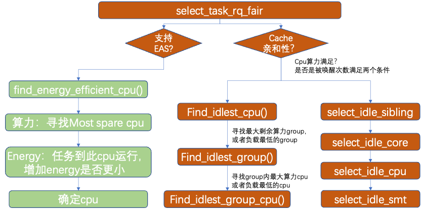
2.3 CFS: select_task_rq_fair
When a process is awakened, it needs to select an appropriate CPU. If EAS is supported, it will choose a more energy-efficient CPU. If EAS support is not enabled, cache affinity and CPU idle degree are considered. If it meets the cache affinity requirements, it will preferentially select a CPU sharing cache (for example, within the same sd_llc domain); otherwise, it will choose a more idle CPU (at this time, CPUs on different NUMA nodes can be selected, not in the same sd_llc domain).
3. Memory Management
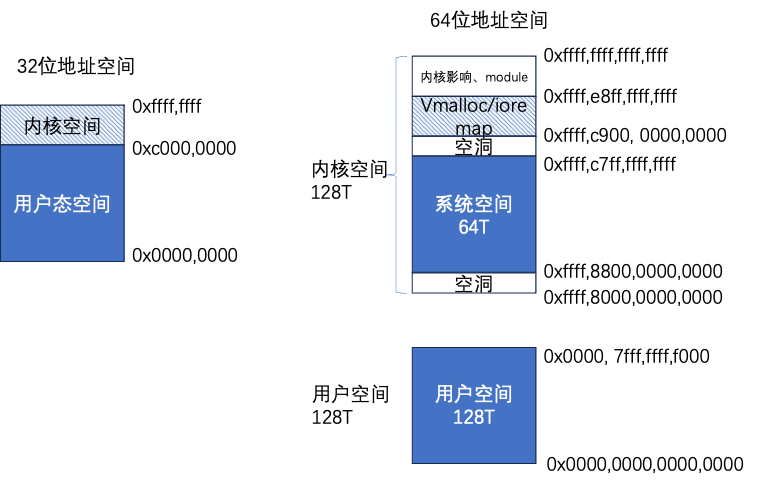
Memory management includes virtual memory and physical memory. 64-bit address space 0x0000,0000,0000,0000.
~0x0000, 7fff,ffff,f000 is the user mode space address, 0xffff,8800,0000,0000~0xffff,ffff,ffff,ffff is the kernel mode space address (excluding some holes).
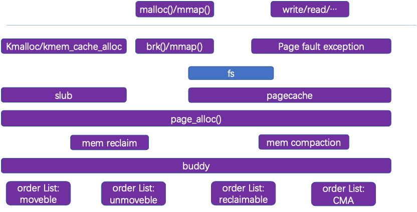
In user mode, memory is allocated through mmap, malloc (actually brk), and different language allocation interfaces. Read, write, and other file system-related system calls can also directly access the page cache.
In the kernel part, memory management consists of the slub subsystem (supporting small memory allocation) and the buddy system (managing all visible pages allocated for kernel use). Functions include memory mapping (map and page faults), memory allocation, memory recovery, memory migration, etc.
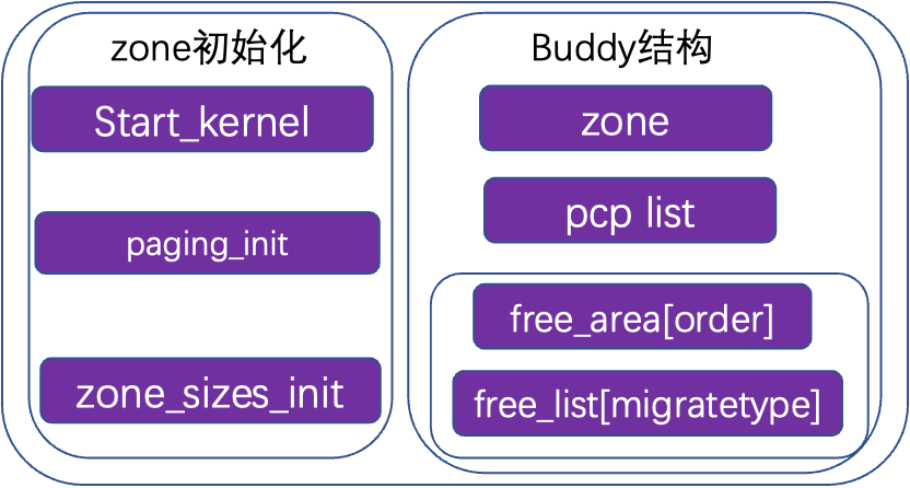
3.1 Physical Memory Types and Organizational Structure
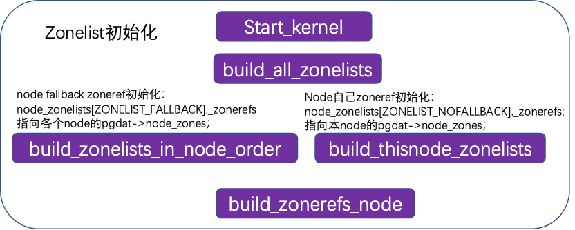
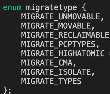
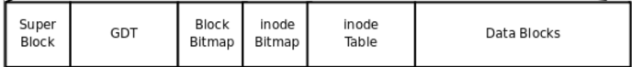
During system startup, memory management is initialized in start_kernel by generating the buddy structure through build_all_zonelists. The buddy system buddy structure includes a pcp list and free_area[], with the pcp list directly managing part of the pages to accelerate single-page memory allocation. Free_area is the main management structure, indexed by order, with each array member including a list of different memory types, such as unmovable/movable/reclaimable/cma, each having a list chain to manage pages of this order size.
Physical memory types can reduce memory fragmentation, and memory types are generally organized by pageblock (1024 pages, 4M), with one pageblock representing one type.
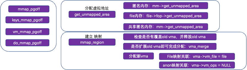
3.2 mmap/malloc and Virtual Memory
mm_struct *mm, mm->mm_rb.rb_node, a red-black tree manages the user mode address space, with allocated virtual addresses managed through the vma structure, which includes a memory region, for example: [100, 2000], added to the red-black tree based on the corresponding virtual address of the vma; when allocating again, find the appropriate gap from the red-black tree (not yet added to the tree and not allocated).
Anonymous addresses are allocated through the process address space mm->get_unmapped_area, while file virtual addresses are allocated through fs, e.g., ext4: thp_get_unmapped_area, mmap_region: typically only allocates virtual addresses, establishing the relationship between virtual addresses and file/anon; during actual access, page faults complete physical address allocation.
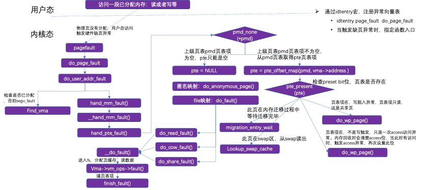
3.3 Page Faults
4. FS
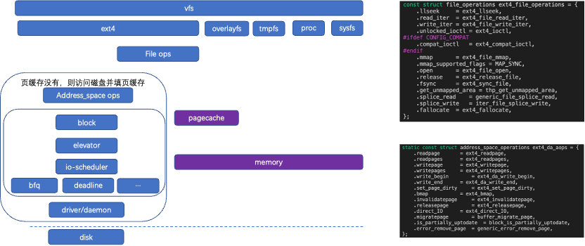
4.1 FS Architecture
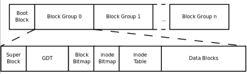
4.2 ext4 Block Group Layout File Organization
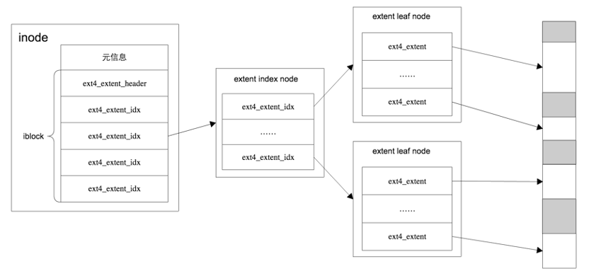
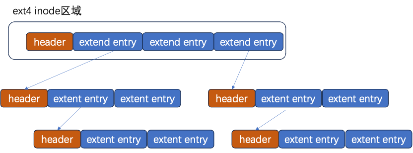
Segments extents are divided into index nodes extent_idx and content leaf nodes extent.
Extent content includes the starting block address and length, with length occupying 16 bytes, thus for a 4KB block, each extent can locate 128M of contiguous addressing space.
Inode defaults to 4 extents, each extent can directly point to a segment of contiguous blocks; if these 4 extents cannot satisfy the file size, the extent becomes extent_idx index node, forming a BTree.
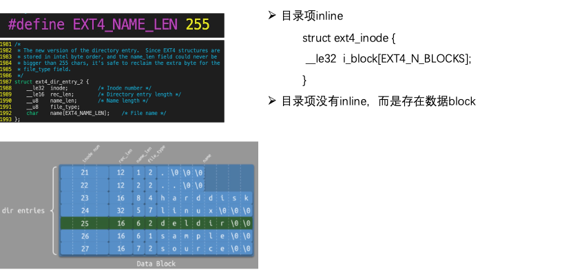
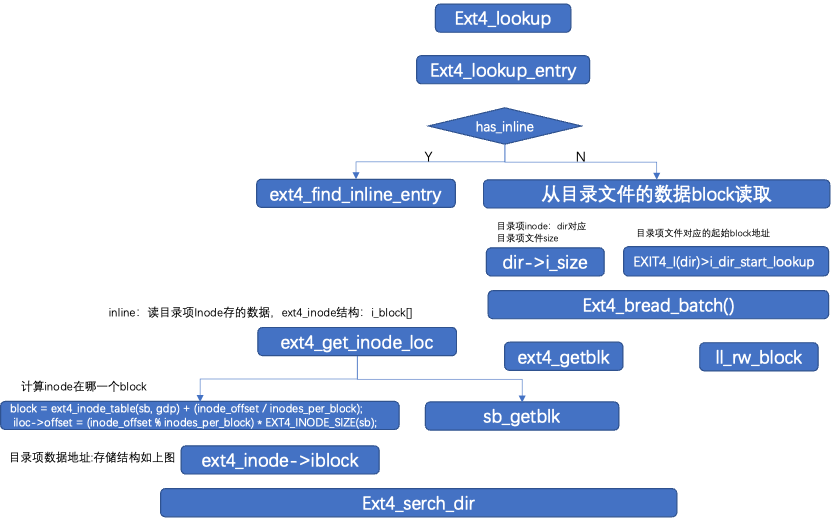
4.3 Directory Entry Structure
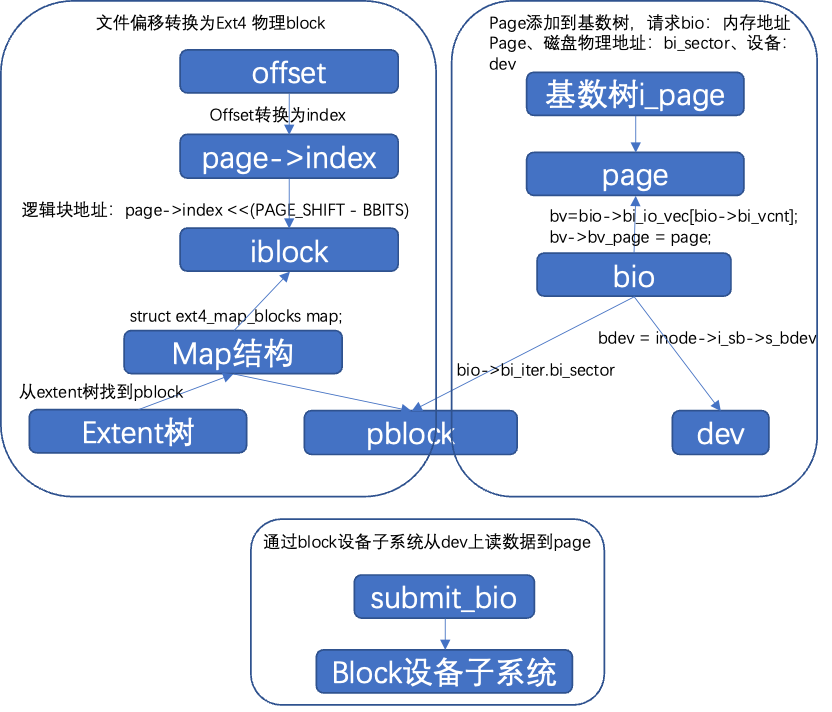
4.4 File: Memory Organization Form
Address space: struct address space: page->mapping
Reading and writing files occurs in two levels: page cache and disk page cache.
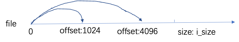
Mapping->i_page is managed through a radix tree. The radix tree index: page->index = offset >> PAGE_SHIFT; pages are added to the tree through index; Index is the file offset (the semantics of index differ for different accesses); for disk (page cache not cached or data is not updated); logical block address: iblock: page->index << (PAGE_SHIFT – BBITS); ext4 is managed through the extent tree.
4.5 Extent Tree: Disk Organization Structure of Files
Inode: corresponds to a file, the structure managing file metadata. The extent tree: EXT4_I(inode)->i_es_tree, the area tree is saved in the ext4 disk inode info structure, adding the area structure to the area tree based on the logical block number, with the area structure: struct extent_status, containing logical block number, physical block number, and the number of blocks in the area, which may be an index block or a leaf node, storing file data through the physical block corresponding to the nodes in the area tree.
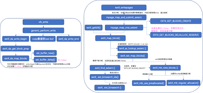
The file system includes write page cache and disk writing. The write page cache corresponds to the file operations operation set, copying data to the page cache. Disk writing writes data back to the disk, corresponding to the fs address space operation set.
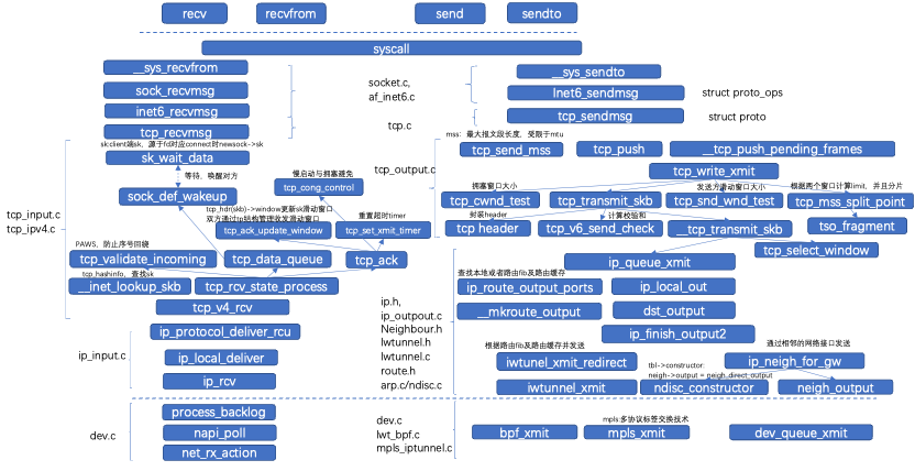
5. Network
5.1 TCP/IP Protocol Hierarchy
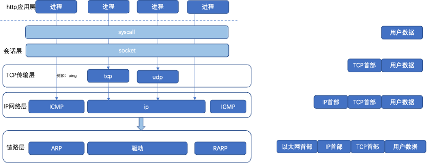
The network protocol stack is layered, divided into the HTTP application layer, session layer, TCP transport layer, IP network layer, and link layer. Each layer protocol corresponds to the components on the right.
5.2 Establishing a Connection
Establishing a Connection
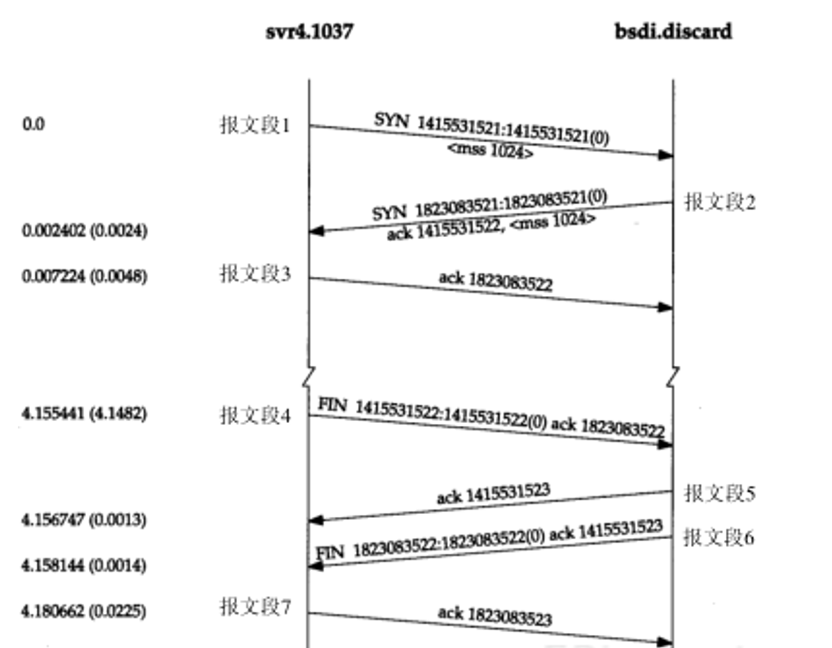
The requesting side (usually called the client) sends a SYN segment indicating the port of the server it intends to connect to and the initial sequence number (ISN, in this example, 1415531521). This SYN segment is message segment 1.
The server replies with a SYN segment containing the server’s initial sequence number (message segment 2) as a response. At the same time, it sets the acknowledgment number to the client’s ISN plus 1 to acknowledge the client’s SYN segment. One SYN will occupy one sequence number.
The client must set the acknowledgment number to the server’s ISN plus 1 to acknowledge the server’s SYN segment (message segment 3).
These three message segments complete the connection establishment. This process is also called the three-way handshake.
Terminating a Connection
Terminating a connection requires four handshakes. This is caused by TCP’s half-close.
TCP connections are full-duplex (i.e., data can be transmitted simultaneously in both directions), so each direction must be closed separately.
The principle is that when one party completes its data sending task, it can send a FIN to terminate that direction of the connection. When one end receives a FIN, it must notify the application layer that the other end has terminated data transmission in that direction. Sending a FIN is usually the result of the application layer closing the connection.
5.3 Concepts
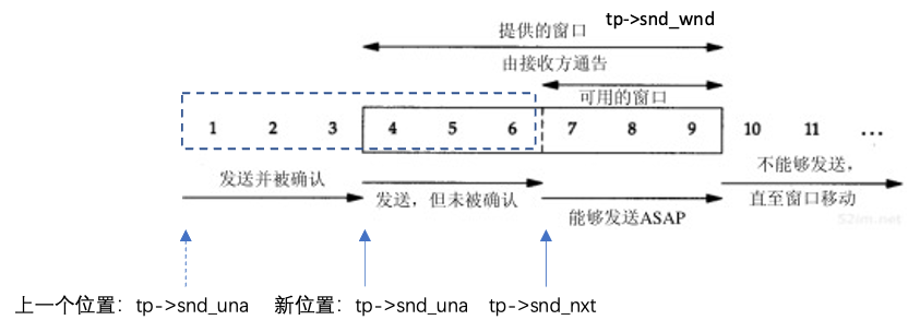
The window is divided into sliding window and congestion window. The sliding window is the window size used by the receiving end to inform the sending end of the receiving end’s cache size, thus controlling the size of data sent by the sending end to achieve flow control. tp->snd_wnd: sending window size, tp->snd_una: the sequence number of the first byte that has been sent but not acknowledged, actually the starting sequence number of the sliding window (if received continuously, it slides to the right) tp->nxt: the sequence number of the first byte that has not been sent but can be sent; tp->rcv_wnd: receiving window size, tp->rcv_nxt: the next expected sequence number to be sent from the sender, rcv_wup: the previous window update rcv_nxt; the sending end’s congestion window does not represent the cache; the congestion window refers to the maximum number of data packets that a source data flow can send within a RTT.
RTT (Round Trip Time)
Round-trip delay, which is the time taken for a data packet to be sent out and receive the corresponding ACK. RTT is connection-specific, and each connection has its own independent RTT.
RTO (Retransmission Time Out)
Retransmission timeout. In the TCP protocol, the basic point of this algorithm is that TCP monitors the performance of each connection (i.e., transmission delay), from which each TCP connection calculates an appropriate RTO value. When the connection delay performance changes, TCP can automatically modify the RTO setting accordingly to adapt to this network change. It uses an adaptive algorithm (Adaptive Retransmission Algorithm) to adapt to changes in internet packet transmission delays.
5.4 Data Transmission
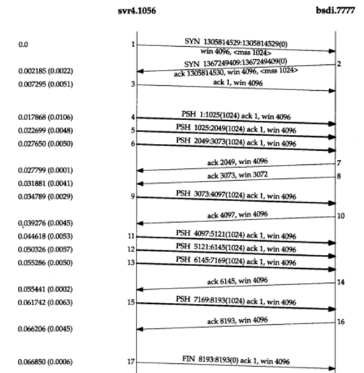
The sender first transmits three data message segments (4~6). The next message segment (7) only acknowledges the first two data message segments (the acknowledgment number is 2048 instead of 3073).
The window size in message segment 8 is 3072, indicating that there are still 1024 bytes of data waiting to be read by the application program in the TCP receiving buffer.
Message segments 11~16 explain the commonly used “acknowledge every other message segment” strategy. When message segments 11, 12, and 13 arrive and are placed in the IP receiving queue, when message segment 11 is processed, the connection is marked as generating a delayed acknowledgment. When message segment 12 is processed, their ACK (message segment 14) is generated, and the delayed acknowledgment flag of the connection is cleared. Message segment 13 causes the connection to be marked again as generating a delayed acknowledgment. However, before the delay timer overflows, message segment 15 is processed, so the acknowledgment is sent immediately.
The ACK in message segments 7, 14, and 16 acknowledges that the two received message segments are very important. When using TCP’s sliding window protocol, the receiver does not need to acknowledge every received packet.
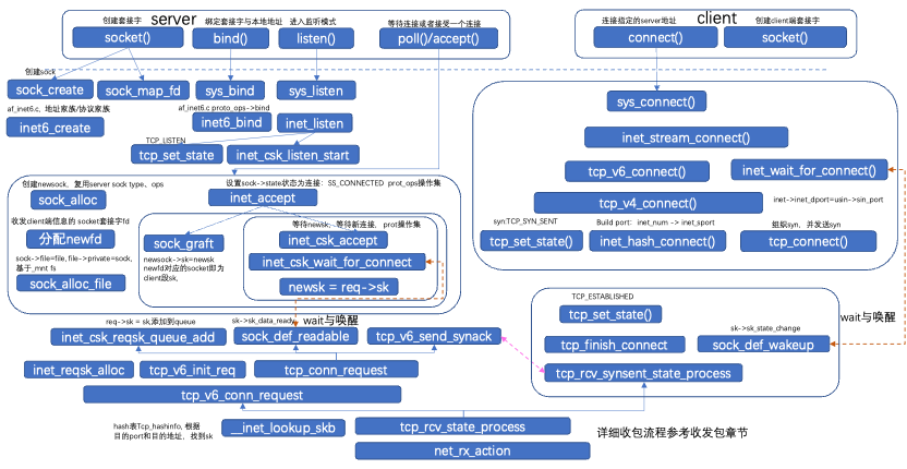
Packet sending and receiving process
5.5 Congestion Algorithm
Slow Start Algorithm
Window cwnd
When congestion occurs, we want to reduce the transmission rate of packets entering the network.
Slow start increases cwnd based on the number of acknowledgments received during this round trip time; when the sender sends a message segment, upon receiving that ACK, the congestion window increases from 1 to 2, allowing two message segments to be sent. When the ACK for these two message segments is received, the congestion window increases to 4, and so on.
Congestion Avoidance Algorithm
The congestion avoidance algorithm requires increasing cwnd by 1/cwnd each time an acknowledgment is received.
Congestion Occurrence
If a timeout occurs and the sender has not received an acknowledgment, then TCP considers that congestion has occurred in the current network. It will handle it using the slow start algorithm.
If the sender receives three consecutive duplicate ACKs, TCP will also consider that congestion has occurred in the current network.
Switch between the two algorithms, at least one algorithm is effective
When congestion occurs (timeout or receiving duplicate acknowledgments), ssthresh is set to half of the current window size. If the congestion is caused by a timeout, cwnd is set to one message segment (this is slow start).
When new data is acknowledged by the other party, cwnd is increased, depending on whether slow start or congestion avoidance is in progress. If cwnd is less than or equal to ssthresh, then slow start is ongoing; otherwise, congestion avoidance is ongoing. Slow start continues until we return to the position where congestion occurred at half the time, then switches to executing congestion avoidance.
5.6 Congestion States
Open State:
The open state is the normal state; in this state, TCP sends packets through an optimized fast path to receive and process ACKs. When an ACK arrives, the sender increases the congestion window according to whether it is less than or greater than the slow start threshold, following slow start or congestion avoidance.
Disorder State:
When the sender receives DACK or SACK, it enters the disorder state; in this state, the congestion window is not adjusted, but when a new segment arrives, it triggers sending a new segment. At this time, TCP follows the principle of packet conservation, meaning a new packet is only sent after an old packet leaves the network; the congestion window remains constant, and the data packets in the network are conserved.
CWR State:
When the sender is notified of congestion notification, it is directly informed!! For example, through ICMP source suppression, etc. When the congestion notification is received, the sender does not immediately reduce the congestion window but decreases it by one segment for each new incoming ACK until the window is reduced to half its original size. During the process of reducing the window, if there is no significant retransmission, it will remain in the CWR state; however, if there is significant retransmission, it will be interrupted by recovery or loss and enter the loss recovery state; the congestion window decreases, and there is no significant retransmission.
Recovery State:
After receiving enough consecutive duplicate ACKs, the sender retransmits the first segment that has not been acknowledged, entering the recovery state. By default, receiving three consecutive duplicate ACKs will enter the recovery state. During the recovery state, the size of the congestion window decreases by one segment for every new acknowledgment received, similar to CWR; during congestion control, this window reduction ends when it equals ssthresh, which is half the window size when entering the recovery state. The sender retransmits the segments marked as lost or sends data according to the packet conservation principle. The sender remains in the recovery state until all data sent in the recovery state is acknowledged, at which point the recovery state will change back to open. Timeout retransmissions may interrupt the recovery state.
Loss State:
When an RTO expires, the sender enters the loss state, and all segments being sent are marked as lost segments, with the congestion window set to one segment. The sender initiates the slow start algorithm to increase the window. The loss state is when the congestion window is increased after being reset to one segment, but the recovery state is when the congestion window can only be decreased. The loss state cannot be interrupted by other states, so only when all data being transmitted in the loss state is acknowledged can it return to the open state, meaning fast retransmission cannot trigger when in the loss state. When an RTO times out, or if the ACK confirmation has already been confirmed by previous SACK, it means that the SACK information we recorded cannot reflect the actual state of the receiver, at which point it will enter the loss state.
5.7 Congestion Transmission Scenarios
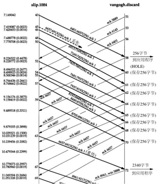
Message segment 45 is lost or damaged; upon receiving message segment 62, which is the third duplicate ACK, data message segment (message segment 63) is retransmitted starting from sequence number 6657. After retransmission (message segment 63), the sender continues normal data transmission (message segments 67, 69, and 71). TCP does not need to wait for the other party to acknowledge the retransmission. When the missing message segment (message segment 63) arrives, the receiving TCP saves the data from 6657 to 8960 bytes in its buffer and delivers this 2304 bytes of data to the user process. All this data is acknowledged in message segment 72. Note that the ACK at this point indicates a window size of 5888 (8192-2304).
5.8 Timer
Creating a Timeout Timer
cp_v4_init_sock
  |-> tcp_init_sock
       |-> tcp_init_xmit_timers
           |-> inet_csk_init_xmit_timers

In initializing the connection, set the handling functions for three timer instances:
icsk->icsk_retransmit_timer's handler function is tcp_write_timer()
icsk->icsk_delack_timer's handler function is tcp_delack_timer()
sk->sk_timer's handler function is tcp_keepalive_timer()
Deleting a Timeout Timer
tcp_done
tcp_disconnect
tcp_v4_destroy_sock
  |-> tcp_clear_xmit_timers
     |-> inet_csk_clear_xmit_timers

void inet_csk_clear_xmit_timers(struct sock *sk) { struct inet_connection_sock *icsk = inet_csk(sk); icsk->icsk_pending = icsk->icsk_ack.pending = icsk->icsk_ack.blocked = 0; sk_stop_timer(sk, &icsk->icsk_retransmit_timer); sk_stop_timer(sk, &icsk->icsk_delack_timer); sk_stop_timer(sk, &sk->sk_timer); }
Activating a Timeout Timer
icsk->icsk_retransmit_timer and icsk->icsk_delack_timer’s activation function is inet_csk_reset_xmit_timer(),
The timeout retransmission timer will be activated in the following situations:
1. When it is found that the SACK segment stored in the receiving buffer of the other end is discarded.
2. When sending a data segment, it is found that there are no segments sent and unacknowledged in the network.
After that, whenever a new data segment acknowledgment is received, the timer is reset.
3. After sending a SYN packet.
4. Some special situations.