This article organizes knowledge related to the TCP-IP protocol through two diagrams. The TCP communication process includes three steps: establishing a TCP connection channel, transmitting data, and disconnecting the TCP connection channel. As shown in Figure 1, a schematic diagram of the TCP communication process is provided.
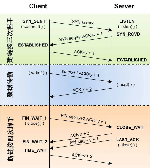
Figure 1 TCP Three-Way Handshake and Four-Way Disconnect
Figure 1 mainly includes three parts: establishing a connection, transmitting data, and disconnecting.
1) Establishing a TCP connection is simple; it can be done through a three-way handshake.
2) After the connection is established, data transmission begins. There are many concepts involved in TCP data transmission: timeout retransmission, fast retransmission, flow control, congestion control, etc.
3) The process of disconnecting the connection is also straightforward, completed through a four-way handshake.
Three-Way Handshake to Establish Connection:
First Handshake: The client sends a SYN packet (seq=x) to the server and enters the SYN_SEND state, waiting for server confirmation;
Second Handshake: The server receives the SYN packet, must confirm the client’s SYN (ack=x+1), and simultaneously send a SYN packet (seq=y), i.e., the SYN+ACK packet. At this point, the server enters the SYN_RECV state;
Third Handshake: The client receives the server’s SYN+ACK packet and sends an acknowledgment packet ACK (ack=y+1) to the server. Once this packet is sent, both the client and server enter the ESTABLISHED state, completing the three-way handshake.
No data is included in the packets transmitted during the handshake process; only after the three-way handshake is completed can the client and server officially begin data transmission. Ideally, once a TCP connection is established, it will be maintained until either party actively closes the connection.
Data Transmission Process:
a. Timeout Retransmission
The timeout retransmission mechanism is used to ensure the reliability of TCP transmission. Each time a data packet is sent, the sent datagram has a seq number. After the receiving end receives the data, it will reply with an ACK to confirm that a particular seq number of data has been received. The sender waits for a period after sending a particular seq packet; if it does not receive the corresponding ACK reply, it assumes the packet is lost and retransmits that data packet.
b. Fast Retransmission
If the receiving end discovers that a data packet has been lost, it will send an ACK packet to inform the sender to retransmit the lost packet. If the sender continuously receives ACK packets with the same number, it will trigger the client’s fast retransmission. Comparing timeout retransmission and fast retransmission, we can see that timeout retransmission involves the sender passively waiting for a timeout, while fast retransmission involves the receiver actively informing the sender that the data has not been received, thus triggering retransmission.
c. Flow Control
This mainly refers to TCP sliding window flow control. There is a field in the TCP header called Window, also known as Advertised-Window, which indicates to the sender how much buffer space the receiver still has available to receive data. Thus, the sender can send data according to the receiver’s processing capacity, preventing overwhelming the receiver. The sliding window can be a mechanism to improve TCP transmission efficiency.
d. Congestion Control
The sliding window is used for flow control. Flow control only focuses on the conditions of the sender and receiver, without considering the overall communication status of the network. Congestion control, on the other hand, considers the entire network. Consider a scenario where the network delay suddenly increases; in this case, TCP’s response is merely to retransmit data. However, retransmission increases the burden on the network, leading to greater delays and more packet losses, creating a vicious cycle that amplifies the situation. Imagine if there are thousands of TCP connections in one network behaving this way, a “network storm” would quickly form, potentially crippling the entire network. To address this, TCP introduces congestion control strategies. The main congestion control algorithms include: slow start, congestion avoidance, congestion occurrence, and fast recovery.
Four-Way Handshake to Disconnect:
First Wave: The actively closing party sends a FIN to close the data transmission from the active party to the passive closing party, indicating to the passive closing party: I will no longer send you data (however, data sent before the FIN packet is still resent if the corresponding ACK confirmation packet is not received). At this point, the actively closing party can still accept data.
Second Wave: The passive closing party sends an ACK to the other party upon receiving the FIN packet, confirming the sequence number as the received sequence number +1 (like SYN, a FIN occupies a sequence number).
Third Wave: The passive closing party sends a FIN to close the data transmission from the passive closing party to the active closing party, indicating to the active closing party, I have finished sending my data and will not send you any more data.
Fourth Wave: The active closing party sends an ACK to the passive closing party after receiving the FIN, confirming the sequence number as the received sequence number +1, thus completing the four-way handshake.
Figure 2 provides a state transition diagram during the TCP communication process, understanding this diagram is key to understanding the TCP-IP protocol.
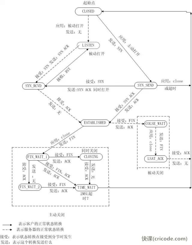
Figure 2 TCP State Transition Diagram
Detailed Interpretation of the State Diagram:
1.CLOSED: The starting point, entering this state during timeout or connection closure.
2.LISTEN: The state of the server waiting for incoming connections, for which the server must call socket, bind, listen functions to enter this state. This is called the passive opening of the application (waiting for the client to connect).
3.SYN_SENT: The client initiates the connection by sending a SYN to the server. If the server cannot connect, it directly enters the CLOSED state.
4.SYN_RCVD: Corresponding to 3, the server accepts the client’s SYN request and transitions from the LISTEN state to the SYN_RCVD state. At the same time, the server must respond with an ACK and send a SYN to the client; alternatively, if the client receives the server’s SYN request while sending its own SYN, it will transition from SYN_SENT to SYN_RCVD state.
5.ESTABLISHED: The server and client complete the three-way handshake and enter this state, indicating that data transmission can begin.
The above describes the state transitions that occur at the server and client during connection establishment. Relatively speaking, it is quite straightforward; if you are familiar with the three-way handshake, understanding the state transitions during connection establishment should be easy.
Next, let’s look at the state transition description when closing the connection, which requires four interactions from both parties, as well as handling some follow-up work (TIME_WAIT state). Note that the actively closing party or the passively closing party does not specifically refer to the server or client; it is relative to who initiates the closure request first:
6.FIN_WAIT_1: The actively closing party transitions from state 5 to this state. The specific action is sending a FIN to the other party.
7.FIN_WAIT_2: The actively closing party, upon receiving the other party’s FIN-ACK (the response to the FIN packet), enters this state.
8.CLOSE_WAIT: The passively closing party enters this state upon receiving the FIN. The specific action is receiving the FIN and sending an ACK. (The reason it is called close_wait can be understood as the passively closing party waiting for the upper-layer application to issue a close connection command.)
9.LAST_ACK: The passively closing party initiates the closure request, transitioning from state 8 to this state. The specific action is sending a FIN to the other party, and upon receiving an ACK, it enters the CLOSED state.
10.CLOSING: When both sides simultaneously initiate closure requests, they transition from FIN_WAIT_1 to this state. The specific action is receiving a FIN request and responding with an ACK.
11.TIME_WAIT: The most complicated state. As can be seen from the state diagram, there are three states that can transition into it, and we will analyze them one by one:
a. Transitioning from FIN_WAIT_2 to this state: In the case where both parties do not simultaneously initiate FIN, the actively closing party enters this state after completing its own closure request and receiving the FIN from the passively closing party.
b. Transitioning from CLOSING state: When both parties simultaneously initiate closure, having both issued FIN requests and received FIN and sent ACK, they transition from CLOSING state.
c. Transitioning from FIN_WAIT_1 state: When simultaneously receiving a FIN (initiated by the other party) and ACK (response to its own initiated FIN), the transition occurs. The difference from b is that the ACK response to its own initiated FIN arrives before the other party’s FIN request, while in b, the FIN arrives first. This situation is the least probable.
Two reasons for the existence of the TIME_WAIT state:
1. To reliably terminate the TCP full-duplex connection.
2. To allow old duplicate segments to dissipate in the network.
Appendix:
Slow Start Algorithm – Slow Start
First, let’s look at TCP’s slow start. Slow start means that a connection just joining the network gradually increases speed; it should not monopolize the road like privileged vehicles right from the start. Newcomers to the highway still need to take it slow to avoid disrupting the order already established by those on the highway.
The slow start algorithm is as follows (cwnd stands for Congestion Window):
1) At the start of the established connection, initialize cwnd = 1, indicating the ability to send one MSS-sized data.
2) Each time an ACK is received, cwnd++; it increases linearly.
3) Every time an RTT passes, cwnd = cwnd*2; it increases exponentially.
4) There is also an ssthresh (slow start threshold), which is an upper limit; when cwnd >= ssthresh, it will enter the “congestion avoidance algorithm” (which will be discussed later).
Thus, we can see that if the network speed is fast, ACKs will return quickly, and RTT will be short, then this slow start will not be slow at all.
Congestion Avoidance Algorithm – Congestion Avoidance
As mentioned earlier, there is also an ssthresh (slow start threshold), which is an upper limit; when cwnd >= ssthresh, it will enter the “congestion avoidance algorithm”. Generally, the value of ssthresh is 65535 bytes; when cwnd reaches this value, the algorithm is as follows:
1) When an ACK is received, cwnd = cwnd + 1/cwnd.
2) Every RTT, cwnd = cwnd + 1.
Thus, it can avoid excessive growth leading to network congestion, gradually increasing and adjusting to the optimal value of the network. It is clearly a linear growth algorithm.
Algorithm in Congestion State
As mentioned earlier, there are two cases when packet loss occurs:
1) Wait for RTO timeout to retransmit the data packet. TCP considers this situation too bad and reacts strongly.
● ssthresh = cwnd /2
● cwnd is reset to 1
● Enter slow start process
2) Fast Retransmit algorithm, which begins retransmission upon receiving 3 duplicate ACKs without waiting for RTO timeout.
● The implementation of TCP Tahoe is the same as that for RTO timeout.
● The implementation of TCP Reno is:
● cwnd = cwnd /2
● ssthresh = cwnd
● Enter fast recovery algorithm – Fast Recovery
As we can see, after RTO timeout, ssthresh becomes half of cwnd, meaning that if packet loss occurs when cwnd <= ssthresh, then TCP’s ssthresh will be halved. When cwnd quickly climbs back to that point, it will gradually increase linearly. We can see how TCP finds the balance point of website traffic quickly and gently through this strong oscillation.
Fast Recovery Algorithm – Fast Recovery
TCP Reno
This algorithm is defined in RFC5681. Fast retransmission and fast recovery algorithms are generally used together. The fast recovery algorithm assumes that if you still have 3 Duplicate ACKs, the network is not that bad, so there is no need to react as strongly as in RTO timeout. Note that, as mentioned earlier, before entering Fast Recovery, cwnd and ssthresh have been updated:
● cwnd = cwnd /2
● ssthresh = cwnd
The actual Fast Recovery algorithm is as follows:
● cwnd = ssthresh + 3 * MSS (the 3 means confirming that 3 data packets have been received)
● Retransmit the data packets indicated by Duplicate ACKs
● If more duplicate ACKs are received, then cwnd = cwnd +1
● If a new ACK is received, then cwnd = ssthresh, and it enters the congestion avoidance algorithm.
If you think carefully about the above algorithm, you’ll realize that this algorithm also has a problem: it relies on 3 duplicate ACKs. Note that 3 duplicate ACKs do not necessarily mean that only one data packet was lost; it is very likely that multiple packets were lost. But this algorithm will only retransmit one, and the remaining packets will have to wait for RTO timeout, leading to a nightmare scenario – timing out reduces the window by half, and multiple timeouts will cause the TCP transmission speed to drop exponentially, and it will not trigger the Fast Recovery algorithm.
TCP New Reno
Thus, in 1995, the TCP New Reno (see RFC 6582) algorithm was proposed, mainly to improve the Fast Recovery algorithm without the support of SACK:
● When the sender receives 3 Duplicate ACKs, it enters Fast Retransmit mode, retransmitting the packet indicated by the duplicate ACKs. If only this one packet was lost, then the ACK returned after retransmitting this packet will acknowledge all the data that has been transmitted by the sender. If not, it indicates that multiple packets were lost. We call this ACK a Partial ACK.
● Once the sender detects a Partial ACK, it can infer that multiple packets were lost, so it continues to retransmit the first packet in the sliding window that has not been acknowledged. This process continues until no more Partial ACKs are received, at which point the Fast Recovery process is truly complete.
We can see that this “Fast Recovery change” is a very aggressive approach, extending both the Fast Retransmit and Fast Recovery processes.
Source: Fast Course Network
Link: http://www.cricode.com/3568.html
ReplyThis Department, read this department’s new student life guide “Let’s Go, Let’s Go, Carrying a Backpack Together~
ReplyZhang Jiang, read Zhang Jiang’s new student life guide “Senior, Can You Sing Twinkle Twinkle Little Star?“
ReplyMilitary Training, read the military training story “Zhang Jiang Girl’s Diary”
ReplyWork, read the schedule “2014 Autumn Campus Recruitment Schedule”
ReplyIntroduction, read “Computer Student Union Department Introduction”
ReplyManagement, read time management methods “2 Minutes a Day, 10 Simple Ways to Change Your Life”
ReplyDevelopment, read the column “My Journey from Soft Girl to Tough Girl – A Sophomore Girl’s Growth Path in Web Development“
=========== About Us ===========
The Student Union of the School of Computer Science at Fudan University is a cross-campus, loving, confident, and mutually supportive collective. In this collective, you will learn how to organize activities, experience the selfless help of seniors, and encounter the most beautiful moments of university life. Welcome to follow us, and best wishes!