Introduction
SPI (Serial Peripheral Interface), UART (Universal Asynchronous Receiver/Transmitter), and I2C (Inter-Integrated Circuit) are common serial communication protocols, each with unique characteristics in hardware interfaces and communication methods, suitable for different application scenarios.
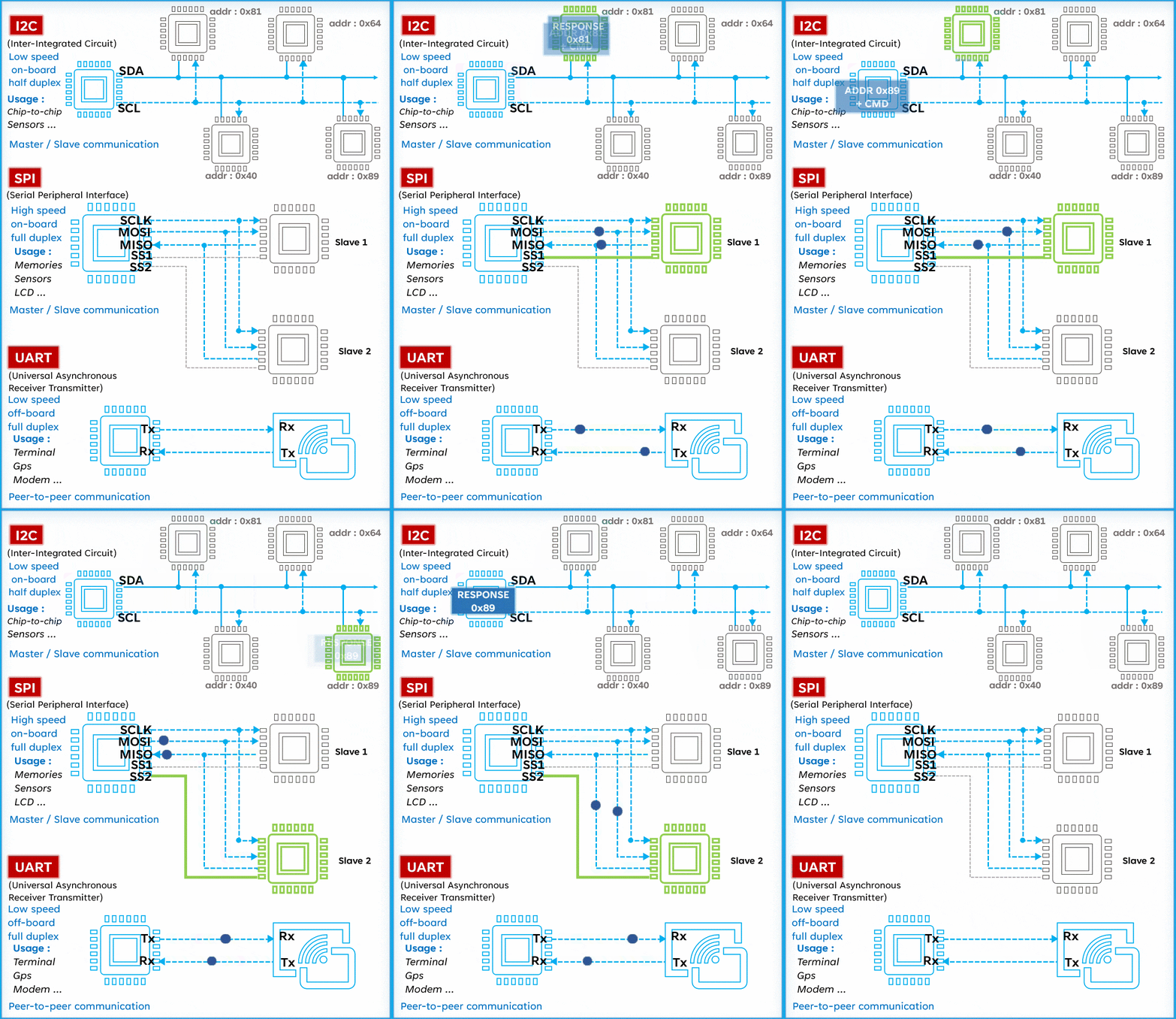
You can get a general understanding of these three communication protocols from the following diagrams:

Next, we will introduce these three communication protocols in detail, along with their differences and applications.
1. SPI Communication
Definition and Characteristics:
SPI is a high-speed, full-duplex, synchronous communication bus that typically uses four lines (MISO, MOSI, SCK, CS), saving chip pins and simplifying PCB layout. It supports multiple data transfer modes and can be configured via control registers. The main features of SPI include full-duplex communication (allowing simultaneous sending and receiving of data, improving communication efficiency), flexible configuration (supporting various transmission modes that can be adjusted based on specific needs), and synchronous transmission (synchronizing data transfer between master and slave devices through a clock signal to ensure data accuracy).
Application Areas:
SPI is widely used in embedded systems, sensor data acquisition, and other fields. Common devices that integrate this communication protocol include EEPROM, FLASH, and AD converters. Additionally, it is also widely used for connecting LCD drivers, MCUs, and other devices.
2. UART Communication
Definition and Characteristics:
UART is a widely used serial asynchronous communication protocol that allows two devices to transmit data over a single bidirectional communication line. UART communication is asynchronous, meaning that the sender and receiver do not share a common clock signal to synchronize their data transmission. UART uses two lines: one for sending (TX) and another for receiving (RX). Data is transmitted serially between these two devices, one bit at a time. The main features of UART communication include full-duplex asynchronous communication, programmable baud rate (the same data transmission rate for sending and receiving), simplicity (only requires two lines), and cost-effectiveness (due to its simplicity, UART is very popular in cost-sensitive applications).
Application Areas:
UART is very common in various electronic devices, such as microcontrollers, computers, modems, and printers. It is often used for long-distance data transmission between two devices, such as communication between a computer and a modem.
3. I2C Communication
Definition and Characteristics:
I2C is a simple bidirectional two-wire bus that is very suitable for efficient interconnection control between microcontrollers and peripherals, or among multiple microcontrollers. It was developed by Philips (now NXP Semiconductors) in the early 1980s and has become a standard for communication between electronic devices. The two lines of I2C include SDA (Serial Data Line) for transmitting information and SCL (Serial Clock Line) for synchronization. One advantage of I2C is that it only requires these two lines for communication, which can effectively utilize resources in complex systems. The main features of I2C include a master-slave communication method (a master device controls the bus and initiates communication, while one or more slave devices respond passively to the commands or requests from the master), bidirectional communication, and lower hardware complexity and communication overhead.
Application Areas:
I2C is widely used in various devices and application areas, such as sensors, memory (like EEPROM), displays, temperature sensors, real-time clocks (RTC), and I/O expansion chips. It is commonly used for short-distance data transmission between integrated circuits, such as communication between microcontrollers and peripherals.
4. Differences Among the Three
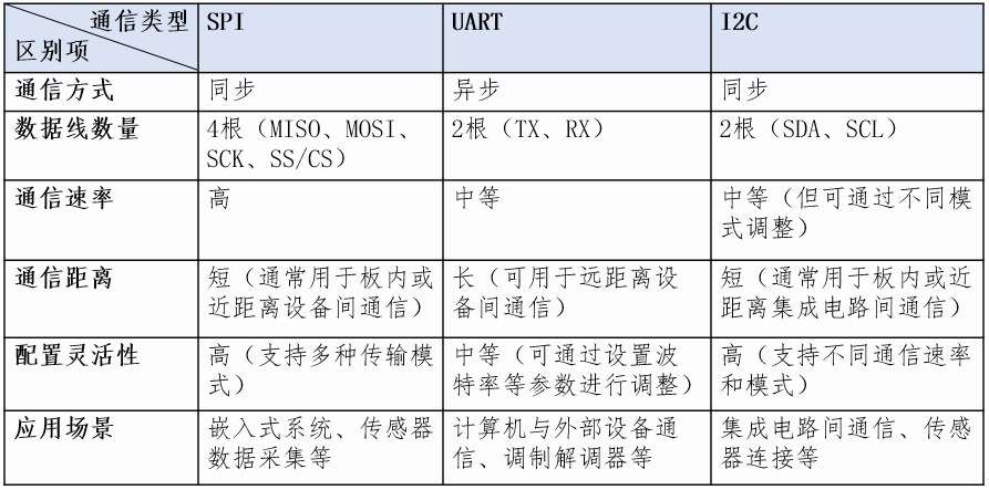
The following are the main differences between SPI, UART, and I2C communication:

Summary
SPI, UART, and I2C are all important serial communication protocols, each with unique characteristics in hardware interfaces, communication methods, communication rates, and application areas. Understanding the features and application scenarios of these communication protocols helps in selecting the appropriate communication method in electronic system design and development to meet system requirements and performance specifications.

Understanding Common Black Box Testing Methods in Software Testing
Understanding Common White Box Testing Methods in Software Testing
Confused About CPU, MCU, MPU, SOC, DSP, ECU, GPU, FPGA? Understanding Their Differences
Confused About SRAM, DRAM, SDRAM, ROM, EPROM, EEPROM, FLASH? A Comprehensive Explanation
How to Conduct Software Code Reviews? A Beginner’s Experience with a Sample Code Review Checklist
Understanding Code Coverage in Software White Box Testing: Statement, Decision, Condition, MCDC, etc.
Little-known Details and Knowledge in C Language (Part I): static, const, volatile, arrays, macros
Concepts, Characteristics, Application Stages, Implementation Processes, Current Status, and Prospects of White Box Testing
Common Scenarios in C Language That May Cause Program Crashes
Overview of Software Testing Phases: Unit Testing, Integration Testing, Configuration Item Testing, System Testing
Where Can IT Professionals Find Side Jobs and Part-time Work?


