1. RSRP Measurement In the 5G (NR) network, the cell’s primary synchronization (PSS), secondary synchronization (SSS) signals, and system broadcast messages are transmitted through SSB (Synchronization Signal Block); after entering the connection state, the terminal measures via CSI, rather than CRS. 3GPP has redefined terminal (UE) measurements in the 5G network, where:
-
In FR-1, the measurement reference point is the antenna connector of the terminal (UE);
-
In FR-2, measurements are based on signals from the corresponding antenna element combination of the given receiving branch.
2. SS-RSRP is the Synchronization Signal Reference Signal Received Power. It is the linear average of the power contributions (in W) of the resource elements carrying SSS. The SS-RSRP measurement time is limited to the duration of the SS/PBCH block measurement time configuration (SMTC) window.
For SS-RSRP to determine the demodulation reference signal of PBCH, if the higher layer indicates, CSI RS can also be used in addition to SSS. The SS-RSRP of the demodulation reference signal using PBCH or CSI reference signals should be measured by the linear average of the power contributions of the resource elements carrying the corresponding reference signals, considering the power scaling of the reference signals; measurements apply to the following cases:
-
RRC_CONNECTED same frequency
-
RRC_IDLE same frequency
-
RRC_IDLE different frequency
-
RRC_INACTIVE same frequency
-
RRC_INACTIVE different frequency
-
RRC_CONNECTED same frequency
-
RRC_CONNECTED different frequency
3. CSI-RSRP is the CSI (Reference Signal) received power, defined as the linear average of the power contributions (in W) of the resource elements carrying the CSI-RS configured for RSRP measurement, considering the measurement frequency bandwidth in the configured CSI-RS case. For CSI-RSRP determination, the CS reference signal transmitted on antenna port 3000 should be used; if CSI_RSRP is used for L1-RSRP, the CSI reference signals transmitted on antenna ports 3000 and 3001 can be used. For same frequency CSI-RSRP measurement, if no measurement gap is configured, the UE is not expected to measure CSI-RS resources outside the active downlink bandwidth. CSI-RSRP measurements apply to the following cases:
-
If CSI-RSRP is used for L1-RSRP, then same frequency RRC_CONNECTED; otherwise,
-
RRC_CONNECTED same frequency,
-
RRC_CONNECTED different frequency
4. SRS-RSRP is the linear average of the power contributions (in [W]) of the resource elements carrying the sounding reference signal (SRS). SRS RSRP should be measured on the configured resource elements within the measurement timing considered for the configured measurement frequency bandwidth.
-
For FR-1, the SRS-RSRP measurement reference point should be the UE’s antenna connector.
-
For FR-2, SRS-RSRP should be measured based on signals from the corresponding antenna element of the given receiver branch.
For FR1 and 2, if the UE uses diversity reception, the reported SRS-RSRP value should not be lower than the respective SRS-RSRP of any individual receiver branch.
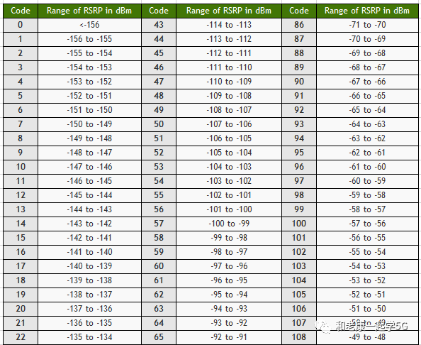
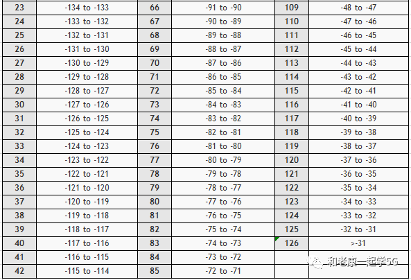
5. RSRP Values and Mapping The terminal (UE) wireless measurement L3 (Layer 3) value range for RSRP in the 5G network is -156~-31dBm, and its L1 and L3 mapping is shown in the table below.