Buses, buses, you always get caught up in them. All signals in this world are the same, but there are thousands of buses, which can be quite a headache.
In general, there are three types of buses: internal buses, system buses, and external buses. The internal bus connects various peripheral chips within the microcomputer to the processor, facilitating interconnections at the chip level; the system bus connects plug-in boards to the system board within the microcomputer, facilitating interconnections at the plug-in board level; and the external bus connects the microcomputer to external devices, allowing the microcomputer to exchange information and data with other devices, facilitating interconnections at the device level.
In addition to buses, there are also some interfaces that are a collection of various buses, or can be described as accommodating all.
SPI (Serial Peripheral Interface): A synchronous serial bus method proposed by MOTOROLA. It is a high-speed synchronous serial port with a 3-4 wire interface, allowing independent and synchronous transmission and reception.
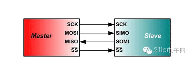
Due to its powerful hardware capabilities, it is widely used in intelligent instruments and measurement and control systems composed of microcontrollers. If speed is not a critical requirement, using the SPI bus mode is a good choice. It can save I/O ports, increase the number of peripherals, and enhance system performance. The standard SPI bus consists of four lines: Serial Clock Line (SCK), Master Input/Slave Output Line (MISO), Master Output/Slave Input Line (MOSI), and Chip Select Signal (CS). Some SPI interface chips may have an interrupt signal line or may not include MOSI.
SPI bus consists of three signal lines: Serial Clock (SCLK), Serial Data Output (SDO), and Serial Data Input (SDI). The SPI bus can connect multiple SPI devices. The SPI device providing the serial clock is the SPI master, while other devices are SPI slaves. Full-duplex communication can be achieved between master and slave devices, and when there are multiple slave devices, an additional slave select line can be added. If simulating the SPI bus with general I/O ports, one output port (SDO), one input port (SDI), and another port depending on the type of device being implemented are required. If implementing master-slave devices, both input and output ports are needed; if only the master device is implemented, only the output port is needed; and if only the slave device is implemented, only the input port is needed.
I2C (Inter-Integrated Circuit): A two-wire serial bus developed by PHILIPS for connecting microcontrollers and their peripheral devices.
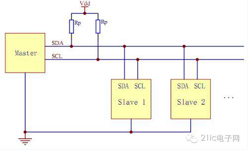
The I2C bus transmits information between the bus and devices using two lines (SDA and SCL), facilitating serial communication between microcontrollers and external devices or bidirectional data transfer between master and slave devices. I2C is an open-drain output, and most I2C implementations are two-wire (clock and data), generally used for transmitting control signals.
I2C is a multi-master bus, allowing any device to function as a master and control the bus. Each device on the bus has a unique address, and depending on their capabilities, they can operate as transmitters or receivers. Multiple microcontrollers can coexist on the same I2C bus.
UART: Universal Asynchronous Receiver-Transmitter, which completes bidirectional communication at standard baud rates, but at a slower speed.
The UART bus is asynchronous, making its structure generally more complex than the previous two synchronous serial ports. It typically consists of a baud rate generator (producing a baud rate equal to 16 times the transmission baud rate), a UART receiver, and a UART transmitter, with hardware consisting of two lines, one for sending and one for receiving.
UART is a chip used to control communication between computers and serial devices. It is important to note that it provides an RS-232C data terminal equipment interface, allowing computers to communicate with modems or other serial devices using the RS-232C interface. As part of the interface, UART also provides the following functions:
Converts parallel data transmitted from the computer into an output serial data stream. Converts serial data from external sources into bytes for use by devices that require parallel data within the computer. Adds parity bits to the output serial data stream and performs parity checking on the data stream received from external sources. Adds start and stop markers to the output data stream and removes start and stop markers from the received data stream. Handles interrupt signals generated by keyboards or mice (which are also serial devices). Can manage synchronization issues between the computer and external serial devices. Some higher-end UARTs also provide input/output data buffers; the latest UART is the 16550, which can store 16 bytes of data in its buffer before the computer needs to process it, while the typical UART is the 8250. Nowadays, if you purchase an internal modem, it typically includes a 16550 UART.
Comparison of SPI, I2C, and UART
Both SPI and I2C are communication methods for short distances, typically between chips or between other components like sensors and chips. SPI and I2C are used for on-board communication; I2C can sometimes be used for inter-board communication, but only over very short distances. For example, some touch screens and mobile LCD screens often use I2C, which can replace standard parallel buses and connect various integrated circuits and functional modules. I2C is a multi-master bus, allowing any device to function as a master and control the bus. Each device on the bus has a unique address, and depending on their capabilities, they can operate as transmitters or receivers. Multiple microcontrollers can coexist on the same I2C bus, and both lines are low-speed transmission.
In contrast, UART is used for communication between two devices, such as communication between a microcontroller-based device and a computer. This type of communication can be done over long distances. UART is faster than the previous two, reaching speeds of up to around 100K, used for communication between computers and devices or between computers, but its effective range is not very long, about 10 meters. The advantages of UART include broad support and a simple programming structure, but with the development of USB, UART is gradually declining.
I2S (Inter-IC Sound Bus) is a bus standard established by Philips for audio data transmission between digital audio devices.
I2S typically consists of three lines (in addition to clock and data, there is also a left/right channel selection signal). I2S is mainly used for transmitting audio signals, such as in STBs, DVDs, and MP3 players.
The I2S standard specifies both hardware interface specifications and the format of digital audio data. I2S has three main signals: 1) Serial Clock SCLK, also known as Bit Clock (BCLK), which corresponds to each bit of digital audio data, with one pulse for each SCLK. The frequency of SCLK = 2 × sampling frequency × number of sampling bits. 2) Frame Clock LRCK (also known as WS), used to switch between left and right channel data. LRCK is “1” when transmitting left channel data and “0” when transmitting right channel data. The frequency of LRCK equals the sampling frequency. 3) Serial Data SDATA, which represents audio data in binary two’s complement format.
Sometimes, to better synchronize between systems, an additional signal MCLK, known as the Master Clock or System Clock (Sys Clock), is also transmitted, which is 256 or 384 times the sampling frequency.
GPIO (General Purpose Input Output) or bus expander simplifies the expansion of I/O ports using industrial standard I2C, SMBus, or SPI interfaces.
When a microcontroller or chipset lacks sufficient I/O ports, or when the system requires remote serial communication or control, GPIO products can provide additional control and monitoring functions. Each GPIO port can be configured as input or output through software. Maxim’s GPIO product line includes GPIOs with 8 to 28 ports, offering push-pull output or open-drain output. They come in a compact 3mm x 3mm QFN package.
The advantages of GPIO (port expanders) include:
Low power consumption: GPIO has lower power consumption (approximately 1μA, while μC operating current is 100μA).
Integrated IIC slave interface: GPIO has a built-in IIC slave interface, allowing it to operate at full speed even in standby mode.
Small package: GPIO devices offer the smallest package size – 3mm x 3mm QFN!
Low cost: You don’t pay for unused features!
Fast time to market: No need to write additional code or documentation, and no maintenance work required!
Flexible lighting control: Built-in multiple high-resolution PWM outputs.
Pre-determined response time: Shorten or determine the response time between external events and interrupts.
Better lighting effects: Matched current output ensures uniform display brightness.
Simple wiring: Only 2 IIC lines or 3 SPI lines are needed.
SDIO
SDIO is an extended interface of the SD type, which can connect not only SD cards but also devices that support the SDIO interface. The port’s purpose is not limited to inserting storage cards. Devices such as PDAs, laptops, and others that support the SDIO interface can connect to GPS receivers, Wi-Fi or Bluetooth adapters, modems, LAN adapters, barcode readers, FM radios, TV receivers, RFID readers, or digital cameras that use the SD standard interface.
The SDIO protocol evolved from the SD card protocol, retaining many aspects of the SD card’s read/write protocol, while also adding CMD52 and CMD53 commands on top of the SD card protocol. As a result, an important distinction between the SDIO and SD card specifications is the addition of a low-speed standard, with low-speed cards targeting applications that support low-speed I/O capabilities with minimal hardware. Low-speed cards support applications like modems, barcode scanners, and GPS receivers, while high-speed cards support network cards, TV cards, and “combo” cards, which refer to memory + SDIO.
Another important distinction between the SDIO and SD card specifications is the addition of a low-speed standard. SDIO cards only require SPI and 1-bit SD transmission mode. Low-speed cards target applications that support low-speed I/O capabilities with minimal hardware expenditure, supporting applications like modems, barcode scanners, and GPS receivers. For combo cards, full-speed and 4BIT operations are mandatory for both the card’s memory and SDIO parts.
In non-combo SDIO devices, the maximum speed is limited to 25M, while combo cards can achieve speeds higher than 25M, similar to the maximum speed of SD cards.
CAN
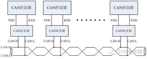
CAN, short for “Controller Area Network,” is one of the most widely used field buses internationally. Initially, CAN was designed for microcontroller communication in automotive environments, exchanging information between various electronic control units (ECUs) in vehicles, forming an automotive electronic control network. For example, the engine management system, transmission controller, instrument equipment, and electronic backbone systems all embed CAN control devices.
In a single network constructed with CAN bus, theoretically, countless nodes can be connected. In practical applications, the number of nodes is limited by the electrical characteristics of the network hardware. For instance, when using the Philips P82C250 as a CAN transceiver, up to 110 nodes are allowed on the same network. CAN can provide data transmission rates of up to 1Mbit/s, making real-time control very easy. Additionally, the hardware’s error detection features enhance CAN’s resistance to electromagnetic interference.
Characteristics of the CAN bus:
1) It can operate in a multi-master mode, allowing any node on the network to actively send information to other nodes at any time, regardless of master or slave, providing flexible communication.
2) Nodes on the network can be divided into different priority levels, meeting various real-time requirements.
3) It employs a non-destructive bit arbitration bus structure mechanism, where if two nodes transmit information simultaneously, the lower-priority node actively stops data transmission, while the higher-priority node can continue transmitting data without being affected.
4) It supports point-to-point, point-to-multipoint, and global broadcast data transmission methods.
5) The maximum direct communication distance can reach 10km (at speeds below 4Kbps).
6) The maximum communication speed can reach 1MB/s (at this speed, the maximum distance is 40m).
Finally, we have covered these tongue-twisting terms; the question is, do you understand them?

1.Course Broadcast | Discussing Memory Structure in Tall Buildings~
2. Let’s give software development engineers some humanistic care!
3.Common Terminology and Concepts in Microcontrollers (If you don’t remember, hurry up and memorize them)
4.Don’t miss the next era while talking about AI~
5. Still looking at programming language rankings? That’s outdated.
6.The 5th issue of “Microcontrollers and Embedded Systems Applications” electronic journal for 2017 is freshly released, with more discounts available!
Disclaimer: This article is a network reprint, and the copyright belongs to the original author. If there are any copyright issues, please contact us, and we will confirm the copyright based on the materials you provide and pay for the manuscript or delete the content.