
liwen01 2024.04.14
Introduction
Various electronic devices around us, such as mobile phones, watches, cameras, and personal computers, seem to start working as soon as they are powered on, from a user experience perspective, this process is generally quite short.
From the perspective of embedded development, whether it is an embedded system or other computer systems, the boot process is relatively complex. Once an error occurs in this process, the device generally cannot operate normally.
(1) Booting Embedded Systems
(1) Memory Architecture Diagram
First, let’s take a look at a memory architecture diagram of an embedded system.
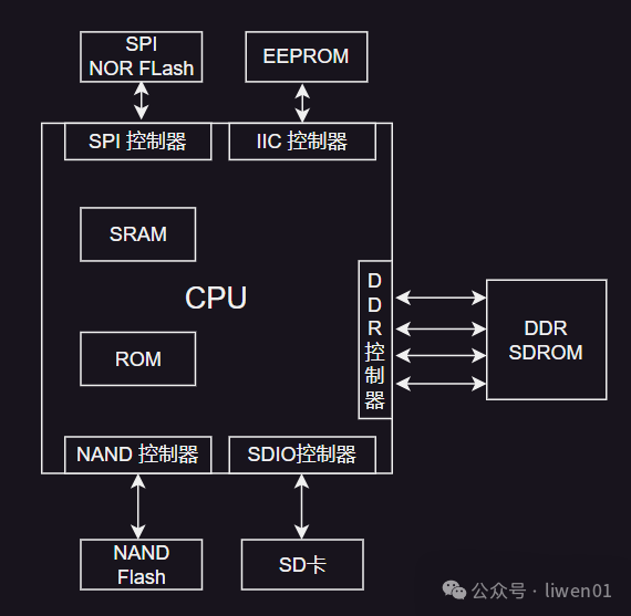
Embedded devices generally have storage media such as NOR Flash, NAND Flash, SD card, and EEPROM, which can be further divided into serial Flash (SPI Flash) and parallel Flash based on the Flash interface. Inside the chip, there are corresponding controllers.
Meanwhile, there is generally a small SRAM and ROM inside the chip, which we usually refer to as internal SRAM and internal ROM.
Our programs, including system programs and application programs, are generally stored on these external storage media.
(2) Boot Process
-
The first program executed when the chip is powered on is not the Boot program placed in the external Flash, but the program on the internal ROM. -
The program in the internal ROM determines which storage device to boot from based on the level state of the BOOT_SEL pin, and then initializes the interface of that storage device. -
After the storage interface is initialized, a small piece of the initial program (generally 4~5K) is loaded into the internal SRAM, and this small piece of code initializes the external DDR memory. -
After the external DDR is initialized, the remaining code in Flash is copied to external DDR, and then it jumps to execute the remaining code in external DDR. -
The BOOT program on DDR initializes the hardware and boots the kernel, which then mounts the root file system. -
The root file system executes the application program and mounts the file system on other partitions of the storage device.
Here are a few key points to note:
-
Not all systems have a BOOT_SEL pin; in some SOCs, it is also used to determine whether it is in programming mode. -
If you analyze the boot linking script, you will find that the code placed at the front 4K of the boot program consists of initialization, code copying, and relocation code, which is generally implemented in assembly. -
Because the internal SRAM space is very small, the program on the internal ROM only copies a small piece of code. -
Steps 1 to 4 of the boot process are referred to as BOOTstrapping or BOOT relocation.
(3) Boot Stages
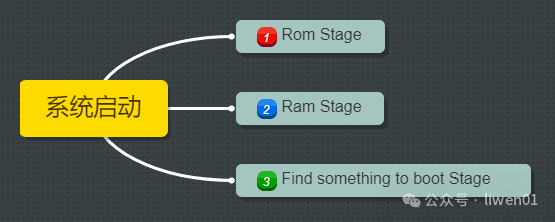
In fact, whether it is an embedded system or other computer systems, the boot process can generally be divided into three stages.
-
ROM Stage -
RAM Stage -
BOOT Stage
ROM Stage: This refers to the ROM program stage inside the processor, mainly responsible for loading a small piece of program at the head of the storage into the internal RAM. This part of the program is generally implemented using assembly.
RAM Stage: This refers to the external DDR that has been initialized, and the program in the memory has been relocated to the external DDR. From here, the program stack space can be established, and C language can start executing.
BOOT Stage: This refers to the initialization of other peripheral hardware and the booting of the system.
(2) Booting Computer Systems
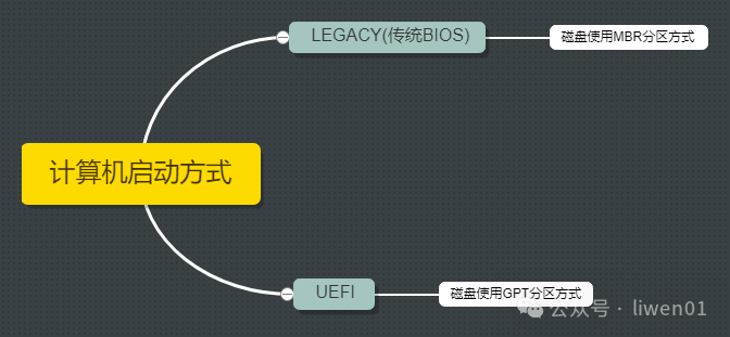
Due to its long history and numerous peripheral types, the boot process of computer systems is somewhat more complex. Depending on the firmware type (BIOS or UEFI) and partition table type (MBR or GPT), the booting of computers can generally be divided into BIOS boot and UEFI boot.
Researching documents, we find that concepts like BIOS, UEFI, and LEGACY are somewhat confusing, with no unified definition. For most people, the program that guides the computer to boot is called BIOS.
Therefore, before this, let’s unify the terminology: the computer boots the system through BIOS, which can be further divided into two methods based on different BIOS firmware and disk partition types: LEGACY (Traditional BIOS) and UEFI Boot.
(1) Introduction to Computer Motherboard Interfaces and Components
To understand the boot process of a computer, we first need to look at what interfaces and components are present on a personal computer’s motherboard.
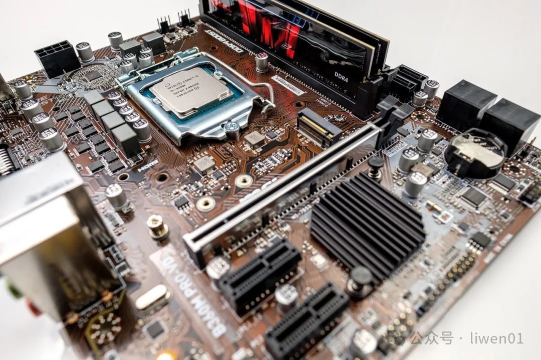

The main components include: Power Supply, CPU, Southbridge and Northbridge Chipsets, BIOS Chip, Disk Interface, and various expansion interfaces and connectors (memory, graphics card, network card, sound card, etc.).
Components related to booting include Power Supply, CPU, South and North Bridge Chipsets, BIOS Chip, Disk, and Memory.
(1) ATX Power Supply: ATX is a specification for motherboards; a power supply that meets the ATX specification is called an ATX power supply. Its function is to convert the AC 220V power into different voltage levels of DC power (5V, 12V, 24V, etc.) used inside the computer.
Additionally, it supports power management. The ATX power supply standard interface (such as PS_ON, PWR_OK, etc.) communicates with the motherboard to manage and control power, including power on, off, sleep mode, and energy-saving functions.
(2) Embedded Controller (EC)
EC (Embedded Controller) is a 16-bit small chip found in laptops. It has different names and slightly different functions on different devices:
-
Desktop computers generally use a Super Input/Output Controller (SIO). -
Mobile phones generally use a Power Management Integrated Circuit (PMIC). -
Laptops use an Embedded Controller (EC).
The main functions of the EC include:
-
Power Management -
Temperature Monitoring and Fan Control -
Input Device Management -
System Monitoring and Fault Detection -
Startup Timing Management -
Battery Management (for laptops)
(3) BIOS Chip
The BIOS (Basic Input/Output System) we often refer to is actually a chip located on the motherboard that stores the BIOS program.
It is mainly responsible for starting and initializing computer hardware and guiding the operating system to boot.
Initially, the BIOS program was stored in ROM; later it was stored in EEPROM; now most are stored in NOR Flash, which allows the BIOS program to be upgraded and updated.
(4) Southbridge and Northbridge
Southbridge and Northbridge refer to two important chipsets on the computer motherboard that work together to connect and manage various hardware components on the motherboard.
Northbridge:
-
Located near the CPU area on the motherboard, responsible for handling tasks related to connecting the CPU and high-speed peripherals. -
Includes memory controller, graphics interface (AGP or PCIe), high-speed system bus (e.g., FSB, Front Side Bus), responsible for managing data transfer between the CPU and memory and controlling the graphics card. -
In newer motherboard designs, with the development of technology, some functions have gradually been integrated into the CPU, and the functionality of the Northbridge has gradually decreased.
Southbridge:
-
Located further away from the CPU on the motherboard, responsible for controlling I/O devices and peripheral buses. -
Includes hard disk controllers, USB controllers, PCI buses, sound cards, network cards, and other peripheral device interfaces, responsible for managing and controlling these devices. -
Handles low-speed operations of I/O devices, corresponding to the high-speed bus of the Northbridge.
With the development of technology and the emergence of new architectures, the functional division between Northbridge and Southbridge has gradually become blurred. Modern chipset designs tend to integrate more functions into a single chip to improve efficiency and reduce the number of components.
(5) Disk
The disk has been introduced earlier.
File System (1): Storage Media, Principles, and Architecture
File System (2): Partitioning, Formatting Data Structures
(6) Extended Introduction
Different motherboard specifications will have variations in interfaces and components.
For desktop computers, there are different working states when powered off and when the device is disconnected from power. In the powered-off state, the BIOS and some other components on the motherboard are still operational, such as some components related to detecting the power-on button.
When the desktop is powered off, its clock is still running, powered by a button battery on the motherboard. The button battery was initially used to power the CMOS, which is a small RAM that stores user-defined BIOS parameters and some parameters of motherboard components.
(2) LEGACY (BIOS) + MBR Boot Method
The LEGACY method can only load MBR partition formatted boot disks. Its booting process can generally be divided into six stages:
-
CPU Power On -
BIOS Hardware Detection -
BIOS Parameter Update -
BIOS Hands Over Control -
Execute MBR Boot Program -
Load Operating System from Active Partition
(a) CPU Power On
-
Pressing the power button starts supplying power to the motherboard and other components, and the CPU begins initialization. -
Once the power stabilizes (the power supply sends a PWR_OK signal), the CPU begins executing instructions from FFFF0H. -
FFFF0H is a mapped address of the BIOS device in the CPU, and its function is to jump to the BIOS code.
(b) BIOS Hardware Detection
-
BIOS checks whether key components in the system are functioning properly, such as memory and graphics card. -
After finding the graphics card, BIOS calls the initialization code on the graphics card to complete its initialization. -
BIOS sequentially checks other components on the motherboard to see if they exist. -
BIOS displays its startup screen. -
Checks the CPU type and frequency and displays it on the screen. -
Checks standard hardware devices in the system, such as hard drives, serial interfaces, and parallel interfaces.
(c) BIOS Parameter Update
-
After completing hardware detection, BIOS updates the ESCD (Extended System Configuration Data). -
This is done only when the system hardware configuration changes.
(d) BIOS Hands Over Control
-
After completing the ESCD update, BIOS checks sequentially for operating systems on disks, CDs, USB drives, etc. (the order can be set by the user in BIOS settings). -
The traditional LEGACY boot method can only recognize storage devices with MBR partitioning. -
After detecting the existence of a storage device, control is handed over to the boot program on the MBR partition.
(e) Execute MBR Boot Program
-
First, copy the 512 bytes of the 0th sector to a safe area in memory for execution. -
Check whether the last two bytes of the 0th sector are “55 AA”; if not, prompt an error. -
Check the partition table for any active partitions. -
If there is an active partition, determine the sector location of the active partition. -
Load the boot sector of the active partition into memory and check if the data is valid. -
If the active sector data is valid, transfer control to the active sector. -
The active sector boots the operating system, and the MBR boot program exits. -
If there is no active partition on the MBR, control is returned to BIOS, which looks for the next storage device.
(f) Load Operating System from Active Partition
-
Once the MBR boot program finds the active partition, it jumps to the location of the active partition, transferring control to it. -
The active partition contains the Boot Loader, responsible for loading the core parts of the operating system. -
The booting of the operating system depends on the type of operating system.
(3) UEFI + GPT Boot Method
The general boot process in Windows systems is:
-
Computer Power On -
BIOS Self-Check -
UEFI Firmware Boot -
Load Boot Device According to RAM Saved Boot Order -
Check if there is an ESP partition on the boot device; if so, load it; if not, check the next storage device. -
Read EFI application information from the ESP partition and load it into the BCD file. -
Read records in the BCD file to load the system.
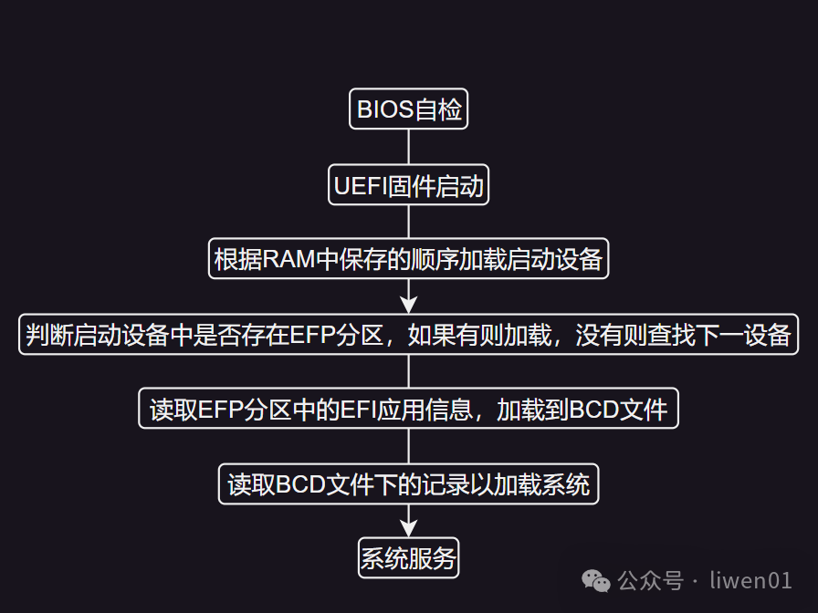
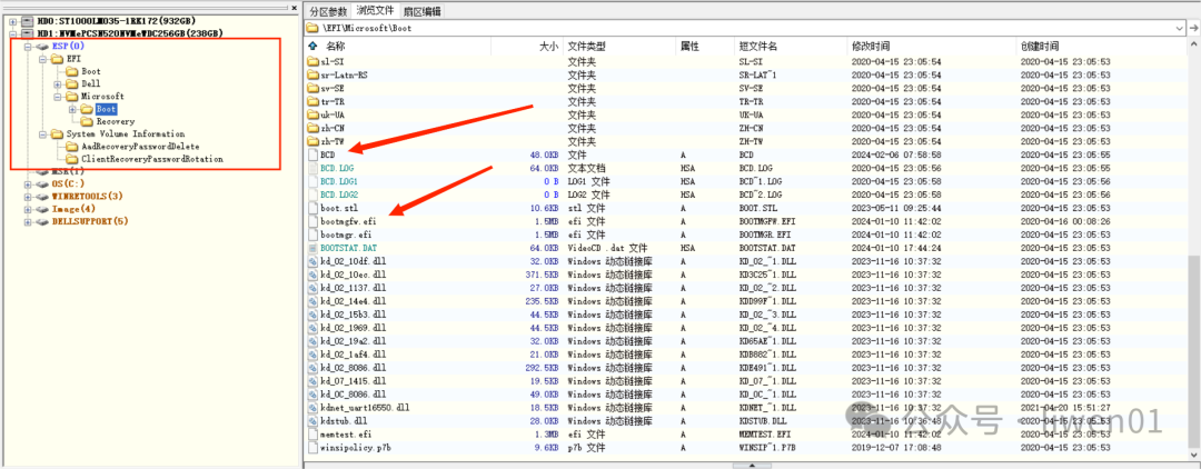
In UEFI boot mode, most of the work is done in the ESP partition.
ESP Partition: ESP (EFI System Partition) is a partition used to store EFI (Extensible Firmware Interface) boot loaders and related boot files. It is an important part of the boot process, containing the operating system boot loader, configuration files, and other boot-related files.
Relevant files include:
-
EFI/Boot/bootx64.efi (or bootia32.efi) -
EFI/Microsoft/Boot/bootmgfw.efi -
EFI/Microsoft/Boot/BCD, which must include BCD and bootmgfw.efi.
UEFI BIOS Program Execution Stages
Generally divided into seven processes:
| Step | Stage Abbreviation | Full English Name | Chinese Name |
|---|---|---|---|
| 1 | SEC | Security Phase | 安全验证阶段 |
| 2 | PEI | Pre-EFI Initialization | EFI前期初始化阶段 |
| 3 | DXE | Driver Execution Environment | 驱动执行环境阶段 |
| 4 | BDS | Boot Device Selection | 启动设备选择阶段 |
| 5 | TSL | Transitional System Load | 操作系统加载前期阶段 |
| 6 | RT | Runtime | 系统运行时阶段 |
| 7 | AL | System Recovery or Shutdown | 系统灾难恢复期或关机阶段 |
1. SEC (Security Verification): Security verification is the first step in the UEFI boot process. In this stage, fixed code of the UEFI firmware is executed, mainly responsible for initializing the CPU, memory, and some basic system hardware.
2. PEI (Pre-EFI Initialization): In this stage, UEFI firmware is responsible for executing more hardware initialization, including DRAM initialization, establishing PEI system services, and preparing for the subsequent DXE stage.
3. DXE (Driver Execution Environment): The DXE stage is where UEFI drivers are loaded and executed. These drivers can be firmware drivers, external device drivers, etc., to provide more hardware support and functionality.
4. BDS (Boot Device Selection): In this stage, UEFI selects the boot device, such as hard drives, CDs, USB drives, etc. Users can configure the boot order through UEFI settings.
5. TSL (Transitional System Load): This stage involves loading the operating system boot loader and preparing to load the operating system. The UEFI boot manager plays a key role in this stage.
6. RT (Runtime): Once the operating system is loaded, the system enters the runtime stage. UEFI still provides some runtime services for the operating system to access hardware resources.
7. AL (System Recovery or Shutdown): This is the final stage of the system, involving disaster recovery, shutdown, or reboot.
(3) Differences in Various Boot Methods
(1) Differences Between Embedded Systems and Personal Computer Booting
The biggest difference between embedded devices and personal computer systems in terms of booting is that personal computers have implemented most of the functions of the embedded device’s SOC in the BIOS. The main reason is that the peripheral interfaces and devices of embedded device SOCs are relatively fixed, and are not as complex as personal PCs, so implementing them in SOC ROM is more efficient.
We can briefly introduce the differences in hardware platforms, boot loaders, and boot times.
1. Hardware Platform:
-
Embedded systems are typically designed for specific purposes, with relatively few hardware resources, such as smart home devices, industrial control systems, or electronic devices. Therefore, their boot processes are usually customized for specific hardware. -
Personal computers are general-purpose computing devices, with more complex and powerful hardware configurations, such as desktop computers, laptops, or tablets.
2. Boot Loader:
-
On personal computers, a boot loader is typically used to start the operating system. This boot loader loads and runs the operating system’s kernel, such as Windows’ NT Loader or GNU GRUB. -
In embedded systems, different boot loading mechanisms may be used, such as simple boot loaders or direct hardware startup, like firmware on the chip.
3. Boot Time:
-
Due to the more complex boot process of personal computers, which includes hardware self-check (POST), boot loader, and operating system loading, their boot times may be relatively longer. -
Embedded systems usually focus more on boot speed and immediate responsiveness, so their boot times are generally shorter.
Overall, embedded systems focus more on customization and efficiency, while personal computers emphasize universality and functionality.
(2) Differences Between LEGACY (BIOS) and UEFI Booting
The main differences lie in the boot method, boot speed, capacity limitations, graphical interface, and security.
1. Boot Method:
-
Legacy BIOS is a traditional boot method that uses the Basic Input/Output System to boot the computer. In this method, the computer first executes the startup program stored in the BIOS firmware and then loads the operating system. -
UEFI is a next-generation boot method that replaces traditional BIOS. UEFI provides a more flexible and powerful boot environment, supporting more hardware features and functions. During the UEFI boot process, the computer executes the startup program stored in the UEFI firmware and can load the operating system and boot loader.
2. Boot Speed:
-
UEFI booting is generally faster than Legacy BIOS booting because UEFI firmware can more efficiently initialize hardware and execute the boot program. -
Legacy BIOS booting may be slower due to its reliance on older technology and may take more time to initialize hardware and execute the boot program.
3. Capacity Limitations:
-
Legacy BIOS has some capacity limitations, such as restrictions on the size of hard disk partitions or boot media. -
UEFI is more flexible, supporting larger capacity hard disk partitions and boot media, thereby better meeting the needs of modern computer systems.
4. Graphical Interface:
-
UEFI typically supports graphical interfaces, providing a more user-friendly interaction experience, such as displaying boot menus or settings interfaces during startup. -
Legacy BIOS is usually text-based, with simpler user interactions, generally requiring keyboard input for selection and settings.
5. Security:
-
UEFI offers more security features, such as Secure Boot, which helps prevent malicious software from loading during system startup. -
Legacy BIOS is relatively simple, with fewer security features, making it more vulnerable to malware attacks.
In summary, UEFI has faster boot speeds, larger capacity support, richer features, and better security compared to Legacy BIOS, making it increasingly widely used in modern computer systems.
Conclusion
In the past, during interviews for embedded software development positions, I was often asked about the system boot process or the uboot boot process. For system engineers, these should be mastered, but for application engineers, I personally believe that understanding the basic processes and concepts is sufficient.
If there are any errors in the above content, please feel free to criticize and correct.