
Unveiling the core principles of waveguides and understanding the challenges behind AR glasses.”
Waveguides are considered essential optical solutions for consumer-grade AR glasses due to their lightweight and high external light transmittance properties, yet their high costs and technological barriers deter many.
With mainstream AR devices like Microsoft’s HoloLens 2 and Magic Leap One adopting waveguide technology and ramping up production, along with frequent funding news from AR optical module manufacturers like DigiLens, NED, and Lingxi Micro, discussions around waveguides have gained significant traction.
So, how does a waveguide work? What are the differences among various types of waveguides available in the market, such as array waveguides, geometric waveguides, diffractive waveguides, holographic waveguides, and multi-layer waveguides? How is it gradually changing the landscape of the AR glasses market? Which waveguide technology do we favor, and why?
Next, let’s have Rokid R-lab optical research scientist, Dr. Li Kun from the University of California, Berkeley, explain it to you.
1
Waveguides, an optical solution born out of the needs of AR glasses
Augmented Reality (AR) and Virtual Reality (VR) have been hot topics in technology in recent years. Their near-eye display systems project virtual images formed by pixels on a display onto the human eye through a series of optical imaging components.
The difference is that AR glasses need to be see-through, allowing users to see both the real external world and virtual information, so the imaging system cannot obstruct the line of sight. This requires an additional optical combiner to merge virtual information with real scenes in a “stacked” manner, complementing and enhancing each other.
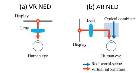 Figure 1. (a) Schematic diagram of the near-eye display system for Virtual Reality (VR); (b) Schematic diagram of the near-eye display system for Augmented Reality (AR).NED:Near-eye display (NED)
The optical display system of AR devices typically consists of miniature displays and optical components. In summary, the display systems used in current AR glasses are combinations of various miniature displays and optical elements like prisms, free-form surfaces, BirdBaths, and waveguides, where the differences in optical combiners are the key factors distinguishing AR display systems.
Miniature displays provide the content for the device. They can be self-emissive active devices like micro-OLEDs and the now-popular micro-LEDs, or liquid crystal displays (including transmissive LCDs and reflective LCOS) that require external light sources, as well as digital micromirror devices (DMD, the core of DLP) based on micro-electromechanical systems (MEMS) technology and laser beam scanners (LBS).
A simple classification of AR optical display systems and product examples is provided below:
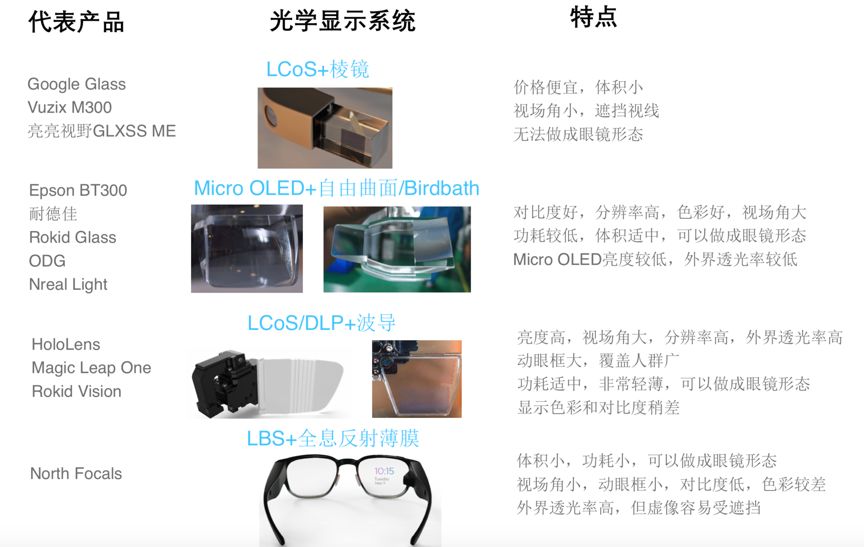
Since this article mainly elaborates on the working principles and characteristics of waveguides, it will not delve into other optical solutions, as many previous articles have already discussed the differences among several options.
Clearly, a perfect optical solution has yet to emerge, which is why the current market is characterized by a hundred schools of thought contending for supremacy, requiring AR glasses product designers to weigh and choose based on application scenarios and product positioning.
We believe that waveguide solutions have the best development potential in terms of optical performance, appearance, and mass production prospects, and may be the only choice for making AR glasses consumer-ready.
2
How waveguides work
Among the aforementioned optical imaging components, waveguide technology is a distinctive optical component born out of the demands of AR glasses, regarded as an essential optical solution for consumer-grade AR glasses due to its lightweight and high external light transmittance properties. With the adoption and mass production of waveguides in devices like Microsoft’s Hololens 2 and Magic Leap One, discussions around waveguides have continued to grow.
In fact, waveguide technology is not a new invention; the optical fibers used in our familiar optical communication systems, which transmit signals, form countless submarine cables connecting across oceans, are a type of waveguide, only transmitting invisible infrared light.
In AR glasses, to ensure that light travels through the waveguide without loss or leakage, “total internal reflection” is key, meaning that light travels through the waveguide like a snake, reflecting back and forth without escaping.
In simple terms, achieving total internal reflection requires meeting two conditions: (1) The transmission medium, i.e., the waveguide material, must have a higher refractive index than the surrounding medium (as shown in Figure 2, n1 > n2); (2) The angle of incidence of the light entering the waveguide must be greater than the critical angle θc.
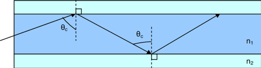
Figure 2. Schematic diagram of the principle of total internal reflection
After the optical system completes the imaging process, the waveguide couples light into its glass substrate and releases it in front of the eyes through the principle of “total internal reflection.”
In this process, the waveguide is responsible only for transmitting the image, typically not performing any “work” (such as enlarging or reducing), which can be understood as “parallel light in, parallel light out,” thus it exists independently from the imaging system.
The characteristics of waveguides offer significant advantages for optimizing headset designs and enhancing aesthetics. With waveguides as the transmission channel, displays and imaging systems can be moved away from the glasses to the forehead or sides, greatly reducing the obstruction of the optical system to external lines of sight and improving weight distribution to be more ergonomic, thereby enhancing the wearing experience of the device.
Below, we list the main advantages and disadvantages of waveguide technology, hoping that readers will gain a better understanding of the underlying reasons after reading this article.
Advantages
• Increases the eye box range to accommodate more users, improves mechanical tolerances, and drives the realization of consumer-grade products – by using one-dimensional and two-dimensional pupil expanding technologies to enlarge the eye box.
• Imaging systems are side-mounted, not obstructing the line of sight and improving weight distribution – waveguide lenses transmit images to the human eye like optical fibers.
• The appearance is more akin to traditional glasses, facilitating design iterations – waveguide forms are generally flat and thin glass sheets whose contours can be cut.
• Provides the possibility of “true” three-dimensional images – multi-layer waveguide plates can be stacked, with each layer providing a virtual image distance.
Disadvantages
• Relatively low optical efficiency – light experiences losses during coupling in and out of the waveguide and during transmission, and a large eye box reduces single-point output brightness.
• Geometric waveguides: Complicated manufacturing processes lead to lower overall yield.
• Diffractive waveguides: Diffraction dispersion causes “rainbow” effects and halos, which are not traditional geometric optics, making the design threshold higher.
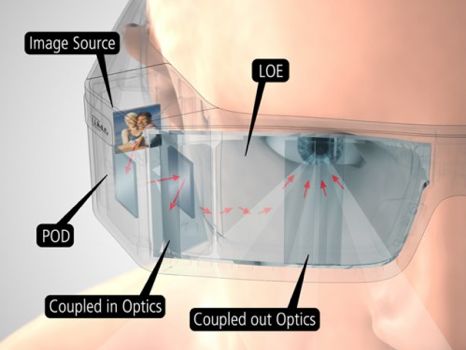
Figure 3. Schematic diagram of the appearance principle of AR glasses based on waveguides
3
Different classifications of waveguides
As mentioned in the second part of the article, the foundation of waveguide structures is a thin, transparent glass substrate (generally a few millimeters or sub-millimeter thick), where light travels through total internal reflection between the upper and lower surfaces of the glass.
If we calculate based on the conditions for total internal reflection, we will find that only a portion of the incident light angles can be transmitted through the waveguide, which determines the final field of view (FOV) range of AR glasses.
In short, the larger the field of view, the higher the refractive index of the glass substrate required to achieve it. Therefore, traditional glass manufacturers like Corning and Schott have been developing specialized high-refractive-index and thin glass substrates for near-eye display markets in recent years, while continuously striving to increase wafer sizes to reduce the unit cost of waveguide production.
With high-refractive-index glass substrates, the differentiation among waveguide types primarily lies in the coupling structures for light entering and exiting the waveguide.
Waveguides can generally be divided into geometric waveguides and diffractive waveguides. Geometric waveguides, also known as array waveguides, achieve image output and eye box expansion through stacked array mirrors, with the representative optical company being Israel’s Lumus, which has not yet produced large-scale commercial glasses.
Diffractive waveguides mainly consist of surface relief grating waveguides manufactured using photolithography and volumetric holographic grating waveguides made using holographic interference technology. HoloLens 2 and Magic Leap One belong to the former, while volumetric holographic grating waveguides use holographic grating elements instead of relief gratings, with Akonia, acquired by Apple, utilizing volumetric gratings, and Digilens also focusing on this direction. This technology is still under development, showing good color performance, but currently has significant limitations on FOV.
It’s important to clarify the misconception surrounding “holographic technology”; in reality, holographic gratings are not capable of true holographic imaging; they simply utilize principles similar to holography to create a “periodic refractive index” by modulating the properties of grating materials using two laser beams to form interference patterns.
4
Working principles and pros & cons of geometric waveguides
The concept of “geometric waveguides” was first proposed by the Israeli company Lumus, which has been dedicated to optimization and iteration for nearly twenty years.
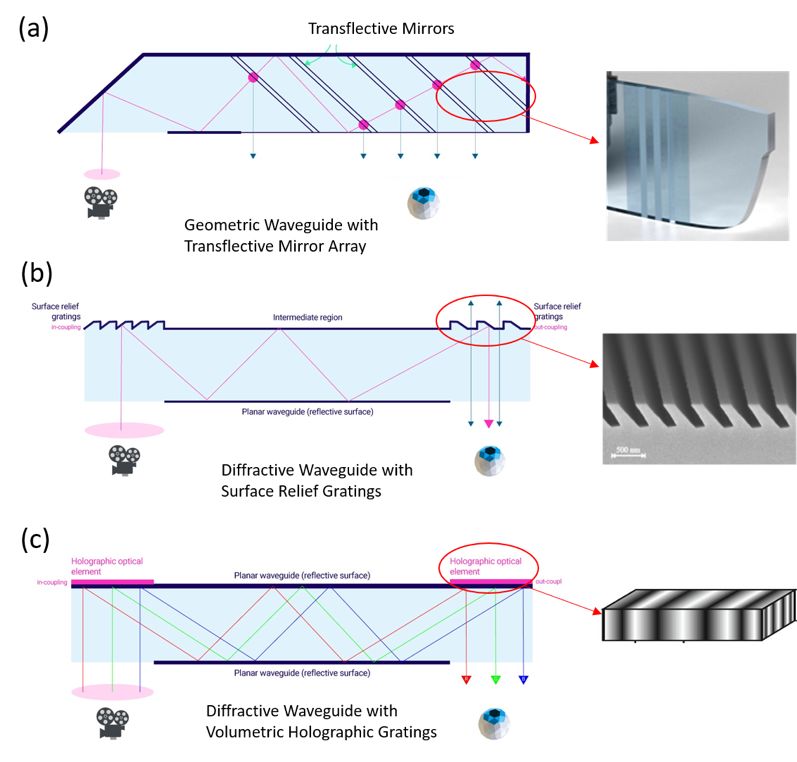
Figure 4. Types of waveguides: (a) Schematic diagram of geometric waveguides and “half-transparent half-reflective” mirror arrays, (b) Schematic diagram of diffractive waveguides and surface relief gratings, (c) Schematic diagram of diffractive waveguides and volumetric holographic gratings. This figure is adapted from https://hackernoon.com/fundamentals-of-display-technologies-for-augmented-and-virtual-reality-c88e4b9b0895
As shown in Figure 4(a), the coupling light entering the waveguide generally comes from a reflective surface or prism. After multiple rounds of total internal reflection, when light reaches the front of the glasses, it encounters a “half-transparent half-reflective” mirror array, which is the structure for coupling light out of the waveguide, known as the “optical combiner” in geometric waveguides.
The “half-transparent half-reflective” (more accurately, “partially transparent and partially reflective”) mirrors are embedded within the glass substrate and form a specific angle with the transmitted light. Each mirror reflects a portion of the light out of the waveguide into the human eye while allowing the remaining light to continue propagating within the waveguide. Then this portion of light encounters another “half-transparent half-reflective” mirror, repeating the “reflection-transmission” process until the last mirror in the array reflects all remaining light out of the waveguide into the human eye.
In traditional optical imaging systems, images usually have a single “exit,” known as the exit pupil. The “half-transparent half-reflective” mirror array essentially replicates the exit pupil multiple times along the horizontal direction, with each exit pupil outputting the same image, allowing the eye to see the image even when moving horizontally. This is known as one-dimensional pupil expansion technology (1D EPE).
To elaborate, suppose the light beam entering the waveguide has a diameter of 4mm. Since the waveguide is responsible only for transmission and does not resize the image, the exit pupil is also a 4mm beam. In this case, the center of the human eye’s pupil can only move within this 4mm range and still see the image.
The problem arises because the distance between the pupils of different individuals can vary from 51mm to 77mm, depending on gender and age. If the optical center of the near-eye display system is designed based on the average pupil distance (63.5mm), it means that a significant portion of people will not see a clear image or receive no image at all when wearing these glasses.
With this pupil expansion technology, the eye box range can typically be expanded from around 4mm to over 10mm. You may wonder if multiple exit pupils would cause overlapping images. Rest assured, the exit pupil surface is merely the “Fourier plane” of the image; the human eye’s pupil will extract complete image information from this plane and project it onto the true “image plane” (retina) using its own lens, meaning that light from the same angle will still converge onto the same pixel (visual cell), preventing overlapping images.
This concept may be a bit difficult to grasp, but it is the essence of how pupil expansion technology works. The enlargement of the eye box resolves many issues in product design, such as mechanical design tolerances, product specifications (whether to create separate models for men and women), and user interaction experiences, significantly advancing AR glasses towards consumer-grade products.
However, there is no free lunch; duplicating the exit pupil increases the total light output area, naturally reducing the amount of light seen at each exit pupil position, which is one reason why waveguide technology has lower optical efficiency compared to traditional optical systems.
Geometric waveguides employ traditional geometric optical design concepts, simulation software, and manufacturing processes without involving any micro-nano structures. Therefore, image quality, including color and contrast, can reach high standards.
However, the manufacturing process is quite complex, one step of which involves the coating process of the “half-transparent half-reflective” mirror array. Since light diminishes during propagation, each of the five or six mirrors in the array requires different reflection/transmission ratios (R/T) to ensure that the output light is uniform across the entire eye box range.
Moreover, since the light propagated through geometric waveguides is typically polarized (due to the working principle of LCOS micro-displays), the number of coating layers on each mirror may reach dozens. Additionally, these mirrors are stacked after coating and bonded with special glue, then cut at an angle to form the shape of the waveguide, where the parallelism between mirrors and the cutting angle will affect imaging quality.
Therefore, even if each step of the process can achieve high yields, the overall yield of these combined dozens of steps remains a challenge. A failure in any step can lead to imaging defects, commonly resulting in background black stripes, uneven output brightness, ghosting, etc.
Furthermore, although the coating process has made the mirror array nearly “invisible,” one can still see a row of vertical stripes (the mirror array) on the lens when the optical system is turned off, which may obstruct some external views and affect the aesthetics of AR glasses.
Next, we will focus on another category of waveguides – diffractive waveguides (Diffractive Waveguide). We will emphasize the working principles of diffractive waveguides, their advantages and disadvantages compared to geometric waveguides, and the two mainstream gratings used in diffractive waveguides – “surface relief gratings (SRG)” and “volumetric holographic gratings (VHG).”
For AR glasses to have the appearance of ordinary glasses and truly enter the consumer market, diffractive waveguides, specifically the surface relief grating solution, is currently the best choice. Many flagship products such as Microsoft HoloLens generations one and two, Magic Leap One, etc., have used and proven the mass production capability of diffractive waveguides. The latest Rokid Vision AR glasses also utilize a binocular diffractive waveguide solution.
The precision and speed required to manufacture diffractive waveguides are expensive, and the equipment must be placed in specialized clean rooms, making manufacturers capable of establishing such production lines few and far between.
Next, let’s explore the mysterious yet important diffractive waveguide technology for AR glasses through the latter part of this content.
5
The core of diffractive waveguides – diffractive gratings
To transmit the virtual image generated by the optical system to the human eye, a coupling-in and coupling-out process for the waveguide is required. In geometric waveguides, these two processes are completed by traditional optical components such as prisms and “half-transparent half-reflective” mirror arrays, which are simple and easy to understand but pose challenges in terms of size and mass production processes. In diffractive waveguides, traditional optical structures are replaced by flat diffractive gratings, which have gained popularity due to the trend of optical components transitioning from millimeter to micro-nano scales, from “three-dimensional” to “two-dimensional” technologies.
So, what are diffractive gratings? In simple terms, they are optical components with periodic structures, which can be high peaks and valleys embossed on the material surface (Figure 4b) or “bright-dark interference patterns” formed inside the material through holographic techniques (Figure 4c), but fundamentally, they cause a periodic change in the refractive index n (refractive index) within the material.
This period is generally at the micro-nano scale, on the same order as the wavelength of visible light (~450-700nm), to effectively manipulate light.
The “spectral separation” of diffractive gratings manifests in two dimensions. As shown in Figure 5, assuming the incident light is a single wavelength of green light, it will be diffracted by the diffractive grating into several diffraction orders, with each diffraction order continuing to propagate in different directions, including reflected diffraction (R0, R±1, R±2,…) and transmitted diffraction (T0, T±1, T±2,…). Each diffraction order corresponds to a diffraction angle (θm, m=±1, ±2, …) determined by the angle of incidence of the light (θ) and the period of the grating (Λ). By designing other parameters of the grating (material refractive index n, grating shape, thickness, duty cycle, etc.), the diffraction efficiency of a specific diffraction order (i.e., a specific direction) can be optimized to the highest, allowing most light to propagate primarily in that direction after diffraction.
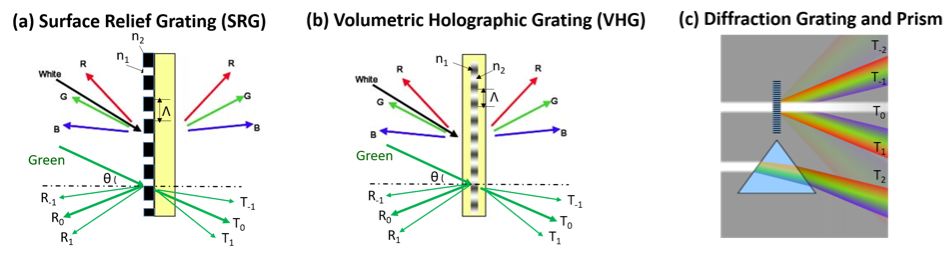
Figure 5. (a) Partial diffraction orders and dispersion of surface relief gratings; (b) Partial diffraction orders and dispersion of volumetric gratings; (c) Comparison of diffractive gratings and dispersive prisms.
This serves a similar purpose to traditional optical devices in altering the direction of light propagation; however, all operations are achieved on a plane through micro-nano structures, thus conserving space and providing greater freedom than traditional optical devices.
For waveguides, this diffraction angle must also meet the total internal reflection conditions within the glass substrate to propagate within the waveguide, which was analyzed in the previous section.
Based on the principle of separating incident light into different diffraction orders, the other dimension of “spectral separation” in diffractive gratings is color dispersion, meaning that for the same grating period, different wavelengths have different diffraction angles (θm). As illustrated in Figure 5, assuming the incident light is white light, the longer the wavelength, the greater the diffraction angle, such that the diffraction angle of red light (R) > green light (G) > blue light (B). This dispersion effect is evident in both reflected and transmitted diffraction.
Does this phenomenon seem familiar? I believe many of us played with prisms as children, where sunlight (white light) is split into a “rainbow” through it; however, the principle of separation in prisms is based on refraction rather than diffraction. Figure 5(c) provides an intuitive comparison of the dispersion phenomenon in diffractive gratings (including multiple diffraction orders and dispersion effects) with that of dispersive prisms, showing that diffractive gratings are far more complex in splitting light into different diffraction levels while also exhibiting dispersion phenomena.
6
Working principles of diffractive waveguides
Having understood the working principles of diffractive gratings, let’s look at how they function within waveguides.
If we recall the one-dimensional pupil expansion achieved in geometric waveguides using “half-transparent half-reflective” mirror arrays, we can simply use an incident grating to couple light into the waveguide in diffractive waveguides, as shown in Figure 6(a), and replace the mirror array with an output grating. This means that the light “swimming” within the waveguide through total internal reflection will release a portion of light into the eye whenever it encounters the grating on the surface of the glass, while the remaining light continues to propagate within the waveguide until it strikes another grating surface, thus achieving one-dimensional pupil expansion.
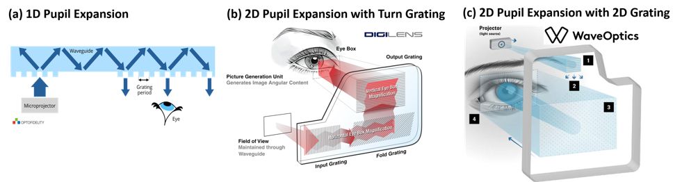
Figure 6. Pupil expansion technology in diffractive waveguides: (a) One-dimensional pupil expansion, (b) Two-dimensional pupil expansion using turning gratings, (c) Two-dimensional pupil expansion using two-dimensional gratings.
However, people are not satisfied with expanding the eye box in one direction (i.e., along the X direction of the inter-pupil distance). Since grating structures can manipulate light properties with greater freedom than traditional optical devices, why not also achieve expansion in the other direction (i.e., along the Y direction of the nose bridge), thus allowing AR glasses to accommodate a wider range of inter-pupil distances and better compatibility for different face shapes and nose heights.
The concept of achieving two-dimensional pupil expansion using turning gratings was proposed by Dr. Tapani Levola at Nokia Research Center in Finland over a decade ago, contributing many valuable papers to the industry, primarily using surface relief gratings (SRG).
Subsequently, this intellectual property was acquired or licensed by Microsoft and Vuzix, meaning that the current HoloLens I and Vuzix Blade utilize similar grating structures and arrangements. As shown in Figure 6(b), another representative optical company, Digilens, also uses a similar three-zone grating arrangement to achieve two-dimensional pupil expansion. When the input grating couples light into the waveguide, it enters a turning grating area, where the grating grooves are angled relative to the input grating. For ease of understanding, let’s assume it’s at a 45-degree angle, functioning like a 45-degree mirror that reflects light coming from the X direction to propagate along the Y direction.
During this turning process, since the light traveling through total internal reflection encounters the turning grating multiple times, each time a portion of the light is turned 90 degrees while the remaining light continues to move horizontally, achieving a similar one-dimensional pupil expansion as shown in Figure 6(a), except the expanded light does not exit the waveguide but continues to propagate in the Y direction until reaching the output grating area.
The output grating structure is similar to the input grating but much larger, and the direction of the grating grooves is perpendicular to the input grating since it is responsible for the two-dimensional expansion. The process is similar to that in Figure 6(a), except it accepts multiple light beams instead of just one. Assuming a single pupil’s input light expands into M x 1 pupils (i.e., a one-dimensional array in the X direction) after passing through the turning grating, then after passing through the output grating, it expands into an M x N two-dimensional matrix, where N is the number of reflections the light undergoes in the output grating area, i.e., the number of expansions.
Using turning gratings to achieve two-dimensional pupil expansion is a straightforward method currently adopted by mainstream products such as HoloLens I, Vuzix Blade, Magic Leap One, Digilens, etc. The area, shape, and arrangement of the three grating regions can be flexibly adjusted based on the optical parameter requirements and design of the glasses.
Another way to achieve two-dimensional pupil expansion is to directly use two-dimensional gratings, where the grating has a periodic structure in at least two directions, transforming the one-dimensional “groove” into a columnar array. The diffractive waveguide company WaveOptics from the UK adopts this structure, as shown in Figure 6(c). The light coupled into the waveguide from the input grating (area 1) directly enters area 3, where the two-dimensional columnar array can simultaneously expand light in both the X and Y directions, while also coupling some light out into the eye during propagation.
It’s easy to imagine that designing this two-dimensional grating is quite complex, as it must balance coupling efficiency across multiple propagation directions while ensuring uniformity of output light across each exit pupil.
The advantage is that there are only two grating regions, which reduces light loss during propagation, and since there is no turning grating, the output grating can occupy a larger area on the limited glass lens, thus increasing the effective eye box range.
WaveOptics’ 40-degree FOV module can achieve an eye box of 19 x 15 mm, the largest among similar products on the market.
7
Analysis of the advantages and disadvantages of diffractive waveguides
Diffractive waveguide technology has significant advantages over geometric waveguides, particularly in the flexibility of design and production of gratings. Whether using surface relief gratings produced through traditional semiconductor micro-nano fabrication processes or volumetric gratings made through holographic interference techniques, they are all accomplished by adding a thin film to the glass substrate and then processing it, allowing for higher mass production capabilities and yields compared to the glass slicing and bonding processes in geometric waveguides.
Moreover, using turning gratings or two-dimensional gratings can achieve two-dimensional pupil expansion, allowing the eye box to cover a wider range of different face shapes in the nose direction, leaving greater tolerance for ergonomic design and optimizing user experience. Since diffractive waveguides also achieve pupil expansion in the Y direction, the dimensions of the optical system in the Y direction are smaller than those of geometric waveguides.
In geometric waveguides, different R/T ratios need to be coated on each mirror in the mirror array to achieve uniform light output across each exit pupil, requiring a very complex multi-step process. For diffractive gratings, it is sufficient to change design parameters such as duty cycle and grating shape, editing the final structure into photolithography, electron beam exposure, or holographic interference masks to “write” the grating film in one step, ensuring uniform light output across multiple exit pupils.
However, diffractive waveguide technology also has its drawbacks, mainly stemming from the high selectivity of diffractive elements for angles and colors, as explained in Figure 5.
First, it is necessary to optimize the diffraction efficiency in one direction across multiple diffraction orders to reduce light loss in other diffraction directions.
Taking the input grating of surface relief gratings as an example, the symmetrical rectangular grating structure diffracts light to the left, which will not be collected and propagated to the eye, effectively wasting half the light. Therefore, inclined gratings or triangular blazed gratings are generally needed to ensure maximum coupling efficiency of light diffracted towards the eye. This inclined surface relief grating requires higher manufacturing standards than traditional rectangular gratings.
Then there’s the challenge of addressing the dispersion issue. As mentioned in Figure 5, different wavelengths correspond to different diffraction angles for the same diffractive grating.
Since the optical system outputs red, green, and blue (RGB) colors, each color contains different wavelength ranges. When they are diffracted through the input grating, as shown in Figure 7(a), assuming we optimize for +1 order diffraction light (i.e., T+1), different diffraction angles θ+1T will correspond to different wavelengths, meaning R > G > B.
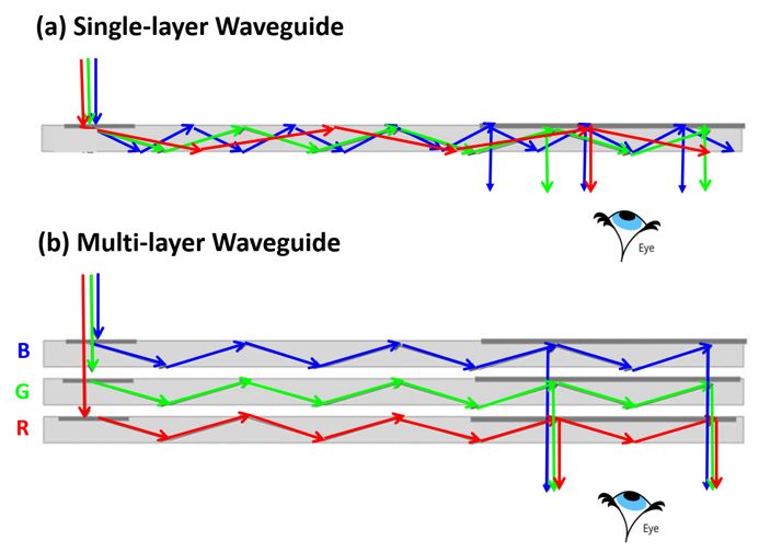
Figure 7. Dispersion issues in diffractive waveguides: (a) Single-layer waveguides and gratings cause “rainbow effects” in output light; (b) Multi-layer waveguides and gratings improve color uniformity in output light.
Due to this angle difference, the path length experienced by light during each total internal reflection will also vary, with red completing fewer reflections than green, while blue undergoes the most reflections. As a result, when the light ultimately encounters the output grating (as indicated by the arrow pointing to the glasses), blue light may couple out three times (i.e., expanding the exit pupil into three), green twice, and red once, leading to uneven RGB color proportions seen by the eye when moving to different positions within the eye box.
Additionally, even the diffraction efficiency of the same color will fluctuate with different angles of incidence, causing the distribution ratio of red, green, and blue light across the entire field of view (FOV) to vary, resulting in the so-called “rainbow effect.”
To mitigate the dispersion issue, as shown in Figure 7(b), red, green, and blue can be coupled into three separate layers of waveguides, with each layer’s diffractive grating optimized for a specific color, thereby improving overall color uniformity at the exit pupil position and reducing the rainbow effect.
However, since RGB LEDs also cover a small range of wavelengths, slight rainbow effects may still be present, as this is a physical characteristic of diffractive gratings, meaning that color uniformity issues can only be continuously optimized through design but cannot be completely eliminated.
The recently released HoloLens II has switched from LED light sources to narrow-bandwidth laser sources, greatly reducing rainbow effects. To make the lenses lighter and thinner, most products on the market merge red and green (RG) into a single layer of waveguide. Some innovative manufacturers have explored new grating designs to incorporate all three RGB colors into a single layer of waveguide, such as the waveguide company Dispelex, but currently, their full-color demos only achieve around 30 degrees FOV.
In summary, the physical process of diffraction itself leads to the existence of dispersion issues, primarily manifested as uneven colors across the FOV and eye box, resulting in the “rainbow effect.” The optimization process for grating design faces challenges in balancing the covered color bands and angle of incidence (i.e., FOV) range, making it difficult to achieve maximum FOV with a single layer of grating.
8
Classification of diffractive waveguides
Currently, surface relief gratings (SRG) dominate the market for diffractive waveguide AR glasses, benefiting from the technological accumulation in the traditional optical communication industry.
The design threshold is slightly higher than traditional optics, primarily because diffractive gratings, due to their micro-nano structure, require physical optics simulation tools, and the ray tracing of light entering the waveguide must be combined with traditional geometric optics simulation tools.
The manufacturing process begins with traditional semiconductor micro-nano fabrication, where the grating master stamp is created on a silicon substrate through electron beam lithography and ion beam etching. This stamp can then be used to imprint thousands of gratings using nanoimprint lithography.
Nanoimprinting involves evenly coating a layer of organic resin on the glass substrate (i.e., waveguide plate), then placing the imprinting master stamp on top. The process is reminiscent of using a wax seal from ancient times to send letters, but here we need to use ultraviolet light to cure the resin. Once cured, we can lift the “stamp,” and the diffractive grating will be formed on the waveguide.
This resin is generally made from materials with high transparency in the visible light band and must have a refractive index similar to that of waveguide glass. Surface relief gratings have been proven to have high mass production capabilities through the emergence of products from Microsoft, Vuzix, Magic Leap, etc., but the precision and speed of reliable electron beam exposure and nanoimprinting equipment are quite expensive and must be placed in specialized clean rooms, resulting in very few manufacturers capable of establishing such production lines in the domestic market.
Fewer manufacturers are working on volumetric holographic grating (VHG) waveguide solutions, including Digilens, which has been making AR helmets for the US military for a decade, Sony, which previously produced monochrome AR glasses, and Akonia, which became mysterious after being acquired by Apple, along with some companies specializing in volumetric grating design and manufacturing.
These manufacturers generally use proprietary formulas, primarily photopolymer and liquid crystal materials or a mixture of both. The production process also involves coating a layer of organic film on the glass substrate, followed by exposing the film through two laser beams to create interference patterns, which induce different exposure characteristics in the material, resulting in the necessary periodicity for forming diffractive gratings.
Due to the limitations of available materials, the achievable Δn (index contrast) is limited, preventing it from reaching the same level as surface relief gratings in terms of FOV, optical efficiency, and clarity. However, it has certain advantages in design barriers, process difficulty, and manufacturing costs, leading to ongoing exploration in this direction within the industry.
9
Conclusion
Alright, after discussing so much, let’s compare the various technical solutions of waveguides to see who will prevail. For convenience, we have summarized a detailed table for horizontal comparison.
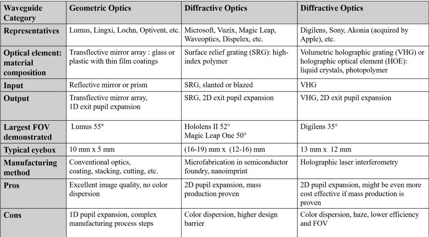
Among them, geometric waveguides are based on traditional optical design concepts and manufacturing processes, achieving one-dimensional pupil expansion. Their leading company is the Israeli firm Lumus, which has demonstrated a 55-degree FOV with excellent imaging brightness and quality.
Unfortunately, the manufacturing process of geometric waveguides is very complex, leading to concerns about final yield; since no consumer-grade AR glasses products have emerged on the market, its mass production capability is still an unknown.
Diffractive waveguides benefit from the development of micro-nano structures and “planar optics,” enabling two-dimensional pupil expansion. The mainstream surface relief gratings have been used by several flagship companies and proven their mass production capabilities through consumer products, with HoloLens II achieving a 52-degree FOV.
Another type of volumetric grating is also developing in parallel. If breakthroughs in materials can enhance optical parameters, future mass production is promising. We believe that diffractive waveguides, specifically the surface relief grating solution, are currently the best choice for AR glasses entering the consumer market.
However, due to the high design threshold of diffractive gratings and the existence of the “rainbow effect,” creating ideal AR glasses remains a significant challenge, requiring collaborative efforts from all industry chains. The Rokid AR team is also committed to exploring breakthroughs and applications in this core technology of AR glasses, aiming to provide users with truly lightweight, portable, and excellent experience AR glasses.
Author: Li Kun, graduated from the Department of Optoelectronics at Zhejiang University and received his PhD from the Department of Electrical Engineering at the University of California, Berkeley. His main research areas include optical imaging systems, optoelectronic devices, semiconductor lasers, and nanotechnology. He is currently an optical research scientist and project leader at Rokid R-lab in the San Francisco Bay Area, USA.
Source: Rokid (ID: Rokid1115), Author: Li Kun.