/ Today’s Tech News /Recently, before Sora ignited the text-to-video track, domestic ByteDance also launched a revolutionary video model – Boximator. Unlike models like Gen-2 and Pink1.0, Boximator can precisely control the actions of characters or objects in the generated video through text. It was revealed that according to experimental data, Boximator maintains the original model’s video quality while possessing very powerful action control capabilities. It can also serve as a plugin to help existing video diffusion models improve generation quality. In response, ByteDance related personnel stated: Boximator is a research project on the technical methods of controlling object movement in the field of video generation, and it is currently not a mature product. There is still a significant gap in picture quality, fidelity, video length, and other aspects compared to leading foreign video generation models./ Author’s Introduction /This article is contributed by Second-hand Programmer, mainly sharing related content on inline hooks inARM64 assembly, which is believed to be helpful for everyone! Thanks to the author for the wonderful article.Original article link:
https://mp.weixin.qq.com/s/-WNNaAyUetiP5UWC5Re0SQ
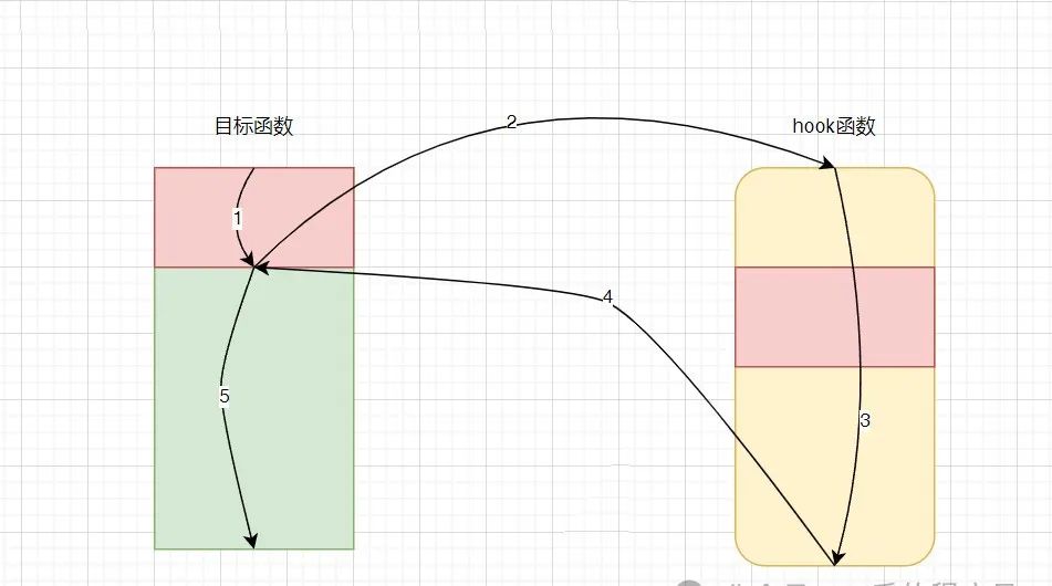
/ Introduction /This discussion focuses solely on inline hooks under ARM64, providing a simple demo merely as a starting point. For those interested in more details, please seek additional resources and explore open-source projects.Inline hooks in ARM64 are considerably more complex compared to ARM, as many instructions are missing and direct access to the PC register is not possible.ARM64 processors are compatible with the ARM32 instruction set, allowing the execution of ARM64, ARM32, and Thumb-2 (Thumb16 + Thumb32) instruction sets on ARM64 processors, but here we will only discuss the ARM64 mode./ Flowchart /Inline hook is to implement a hook on a specified function, and its general process is illustrated in the following diagram:First, it is necessary to replace the head instruction of the target function, modifying the value of the PC to the address of the hook function and jumping to execute it.For the overwritten instructions, we will execute them within the hook function, corresponding to the red part in the diagram. Many issues may arise here, and those interested can find relevant information.After the hook function has executed, the value of the PC needs to be modified to the address of the next instruction after the overwritten instruction, and then jump to execute it.During these processes, we need to ensure that the values of the registers before and after executing the hook function remain the same, and that the executed overwritten instructions do not modify the registers unless their values are stored first./ Solution Design /
Step 1 – Original Program Instrumentation
The design idea is: first, the fundamental requirement for instrumentation code is to have a jump function. In ARM64, the PC cannot be directly read or written; so how do we change the PC? Typically, there are two types of jump methods: relative addressing and direct addressing.Relative addressing has distance limitations; since our hook program is also a shared object, its position is not fixed, and the target shared object’s position is also not fixed, the distance between these two shared objects is also variable, making relative addressing unwise.Direct addressing allows ARM64 to use BR X?? to directly jump to the 64-bit address stored in the X?? register. Hence, the plan should be:
LDR X0, [TARGET_ADDRESS]
BR X0
However, this will overwrite the original value in X0, so we need to store some values of X0:
The first instruction above stores X1 and X0 on the stack; X1 is merely redundant, intended to satisfy the ARM64 stack’s requirement for 16-byte alignment, as there are no available PUSH instructions.Since we altered the stack, we need to balance it, so when we finally return to the original program, we need to modify the stack values back:
STP X1, X0, [SP, #-0x10]
LDR X0, [TARGET_ADDRESS]     ; TARGET_ADDRESS is a dynamic value, more instructions will be needed after compilation to achieve this
BR X0
LDR X0, [SP, -0x8]
Here, there is a slight difference from our envisioned process; we need to wait for the hook function to finish executing before jumping to the last instruction above to restore the value of the X0 register.It is important to note that our instrumentation instructions must consist of at least 4 instructions, occupying 16 bytes. If the function body is too small, the hook will lead to errors. Thus, this is an optimization point.
Step 2 – Hook Program
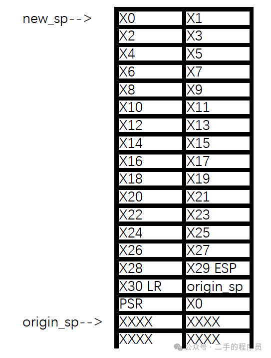
We first need to save the values of all registers. After saving the register values, we can utilize these registers. The saving structure is as follows:The corresponding instructions are as follows:
sub     sp, sp, #0x20          ; sp = sp - 0x20, moving the pointer up by 2
mrs     x0, NZCV               ; store the status register value in x0
str     x0, [sp, #0x10]        ; store the x0 (status register) value at sp + 0x10, which is the PSR in the diagram
str     x30, [sp]              ; store the x30 value at sp, which is the X30 LR in the diagram
add     x30, sp, #0x20         ; X30 = sp + 0x20
str     x30, [sp, #0x8]        ; store the value at sp + 0x20 at sp + 0x8, which is the original sp value in the diagram
ldr     x0, [sp, #0x18]        ; set x0 to point to the stack top
sub     sp, sp, #0xf0          ; allocate space to store X0 - X29 registers
stp     X0, X1, [SP]
stp     X2, X3, [SP,#0x10]
stp     X4, X5, [SP,#0x20]
stp     X6, X7, [SP,#0x30]
stp     X8, X9, [SP,#0x40]
stp     X10, X11, [SP,#0x50]
stp     X12, X13, [SP,#0x60]
stp     X14, X15, [SP,#0x70]
stp     X16, X17, [SP,#0x80]
stp     X18, X19, [SP,#0x90]
stp     X20, X21, [SP,#0xa0]
stp     X22, X23, [SP,#0xb0]
stp     X24, X25, [SP,#0xc0]
stp     X26, X27, [SP,#0xd0]
stp     X28, X29, [SP,#0xe0]
Since there are no LDM/STM instructions, we can only store a large number of registers to the stack one pair at a time.Next, we can execute the previously overwritten code; this will not be demonstrated here, but a demo will be written later.Then we will restore the registers:
ldr     x0, [sp, #0x100]     ; assign the address storing PSR to X0
msr     NZCV, x0             ; restore the value of the status register

ldp     X0, X1, [SP]         ; restore the values of X0 and X1
ldp     X2, X3, [SP,#0x10]
ldp     X4, X5, [SP,#0x20]
ldp     X6, X7, [SP,#0x30]
ldp     X8, X9, [SP,#0x40]
ldp     X10, X11, [SP,#0x50]
ldp     X12, X13, [SP,#0x60]
ldp     X14, X15, [SP,#0x70]
ldp     X16, X17, [SP,#0x80]
ldp     X18, X19, [SP,#0x90]
ldp     X20, X21, [SP,#0xa0]
ldp     X22, X23, [SP,#0xb0]
ldp     X24, X25, [SP,#0xc0]
ldp     X26, X27, [SP,#0xd0]
ldp     X28, X29, [SP,#0xe0]
add     sp, sp, #0xf0         ; set sp to point to X30 LR location

ldr     x30, [sp]             ; restore X30 register
add     sp, sp, #0x20         ; restore the sp value, origin_sp is unused
After restoring the registers, we need to jump back to the original function to continue executing the last line of the overwritten instruction:
ldr   x0, ret_addr
br    x0
Thus, a framework for a hook solution has been designed./ Example /We will attempt to perform an inline hook on the fopen function in libc.so.
Run the compiled program to confirm that the address can be correctly obtained. If it is a 32-bit shared object, this address might be an odd number, indicating it is in thumb mode.Next, we will write the hook function. It is important to note that compilers generate prolog and epilog code for general functions, and since we need complete control over the assembly instructions generated by the hook function, we need to use naked functions or write assembly directly.
void __attribute__((naked)) hook_func()
{

}
We need to overwrite the head instructions of the fopen function, which requires modifying the .text section. Since the .text section is not writable, we need to use the mprotect function to gain write permissions.
It can be seen that indeed one segment’s permissions have changed to rwx.Now, we can start overwriting instructions. However, a frustrating point arises: in ARM32, it is very simple, just use LDR:
LDR pc, [pc-4]
hook_func_addr
The above two instructions mean that the first instruction assigns the content of the next instruction to the PC, so the second instruction is not a real instruction but the address of the hook function, allowing for a very simple implementation of the hook function’s jump.In ARM64, we cannot manipulate the PC register directly; we can only use the B instruction to jump:
LDR X0, [TARGET_ADDRESS]
BR X0
LDR X0, [SP, -0x8]
Here arises a problem: TARGET_ADDRESS is a dynamic value, and we cannot determine it at compile time. So what should we do? We need to adopt a special writing method:
STP X1, X0, [SP, #-0x10]   ; store x0, x1
LDR X0, 8                  ; load the content at the address pc + 8 into x0
BR X0                      ; jump to the address corresponding to x0
ADDR(64)                   ; target address
LDR X0, [SP, -0x8]         ; set x0 to point to the stack top
ADDR is the address of the hook function, assigning this address to X0 and then using BR X0 to jump. Note that this address occupies 8 bytes, so it effectively corresponds to 6 instructions.LDR X0, 8 needs special explanation; this patch program generated by IDA produces an offset relative to the base address of the shared object, not relative to the PC. To generate instructions relative to the PC, the following writing method is needed:
LDR X0, .+8
I saw an open-source project that directly used LDR X0, 8, and I’m unsure if it’s a difference in the assembly language writing method.In IDA, generate these instructions in assembly code and overwrite the first 6 instructions of the fopen function:
// Instructions are 4 bytes, using uint32, addresses use unit64

// STP X8, X0, [SP, #-0x60]  -> E8 03 3A A9
(*(uint32_t *)(hook_addr + 0)) = 0xA93A03E8;

// LDR X0, 8 -> 40 00 00 58
(*(uint32_t *)(hook_addr + 4)) = 0x58000040;

// BR X0  -> 00 00 1f d6
(*(uint32_t *)(hook_addr + 8)) = 0xd61f0000;

// ADDR  -> 00 00 1f d6, here needs to be 64-bit
(*(uint64_t *)(hook_addr + 12)) = hook_func;

// The overwritten instruction operated on sp, so we need to calculate the sp value (sp - 0x60 + 0x50)
// LDR X0, [SP, #-0x10]  -> E0 03 5F F8
(*(uint32_t *)(hook_addr + 20)) = 0xF85F03E0;
Here are some details to note:
We stored X8 and X0 at the position sp – 0x60 because the overwritten fopen instruction would operate on sp. Its function stack size is 0x50, so I placed X8 and X0 in a position that fopen cannot reach, to avoid losing our stored data due to the overwritten instruction modifying stack data.
Store X8 because later, when generating the instruction to jump back, GCC uses X8.
Store X0 because we use the X0 register for jumping, so it needs to be saved and restored later.
Once the overwrite instructions are set, we can write the hook function:
The hook function I wrote is relatively simple, mainly doing three things:
Get the value of X0, as X0 is the first parameter; we can assign X0 to a global variable and print it to check if the hook was successful.
Execute the overwritten instructions, which is straightforward; just copy the first six instructions of fopen.
After execution, we need to jump back to fopen to continue executing; we first calculate the instruction address, then use inline assembly to generate the corresponding instructions.
Besides using inline assembly, we can also implement it directly in assembly, which I am not very familiar with, but I will briefly introduce it. First, define a variable in the assembly file:
.global _shellcode_start_s
Then, use this variable as a label:
_shellcode_start_s:

    sub     sp, sp, #0x20
In another C file, we can directly reference this variable using extern:
extern unsigned long _shellcode_start_s;

void *p_shellcode_start_s = &_shellcode_start_s;
In this way, we obtain the starting address of the hook function. Interested readers can check out relevant open-source projects on GitHub./ Source Code /
It can be seen that we successfully hooked the fopen function:
data is the first 4 bytes of the so file, which is .elf
x0 and x1 are parameters
Recommended reading:My new book, “The First Line of Code, 3rd Edition,” has been published!I thought I discovered a bug in Android 14, but…Implementing a smooth and fluid page expansion and contraction effect animation on AndroidFeel free to follow my public accountLearning technology or submitting articles
Long press the image above to scan the QR code to follow