To master the STM32 microcontroller, one cannot do without serial communication. Serial communication uses a protocol called the serial communication protocol to manage data transmission, which controls the data flow during transmission, including data bits, baud rate, parity bits, and stop bits. Due to its simplicity and ease of use, serial communication is widely applied in various product interactions.
However, when using serial communication, we do not know how much data the other party will send or when the data will be finished sending. In simple terms: how to ensure that a complete frame of data is received?
The data sent via serial communication can vary in length. If it is not completely received, it will certainly affect the processing of subsequent tasks. Common methods for receiving variable-length data include:
1. Fixed Format
For example, both parties agree that a data frame starts with AA BB and ends with BB AA. Thus, when the slave receives data, upon receiving AA BB characters, it knows that the other party is about to send a data packet, and it saves the subsequent data until it receives BB AA.
This method is simple and efficient, but the downside is that every character needs to be checked, wasting CPU resources and increasing power consumption.
2. Receive Interrupt + Timeout Check
When a piece of data is received via serial communication, it will trigger a receive interrupt. But how do we determine that the data has been completely sent?
Generally, there will be a time interval between two data frames. Therefore, we can use a timer; if no new character is received within a fixed time period, we assume that a data frame has been fully received.
3. Idle Interrupt
When the serial port is idle, meaning no new data has been received for a period, an idle interrupt will be triggered. Observant students may notice that the idle interrupt is essentially the same as the timeout check mentioned above, except that the idle interrupt is hardware-supported, while the timeout check needs to be implemented by ourselves.
Thus, once an idle interrupt is received, we can assume that a complete frame of data has been received.
However, not all MCUs have the idle interrupt feature; generally, only higher-end MCUs have it, while lower-end MCUs do not.
1. What is an Idle Interrupt?
As mentioned earlier, when a byte of data is received, a receive interrupt is triggered, corresponding to the 5th bit of the serial port status register being set to 1; if the serial port is idle, an idle interrupt will be triggered, and the 4th bit will be set to 1, as shown in the figure below:
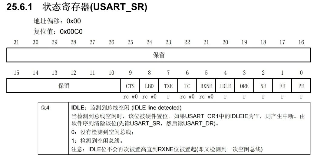
In the interrupt service function, remember to clear the IDLE bit; otherwise, it will keep triggering the idle interrupt, affecting subsequent task processing.
2. DMA
2.1 What is DMA?
Head-scratching description:
“
DMA (Direct Memory Access) provides high-speed data transfer between peripherals and memory, memory and memory, and peripherals to peripherals. It allows hardware devices of different speeds to communicate without relying on the CPU, during which the CPU cannot work with memory.
”
Simple description:
It is a data mover!!
2.2 Significance of DMA
It replaces the CPU in moving data, relieving the CPU of its workload.
-
Data movement is time-consuming;
-
Data movement has high efficiency requirements (data must be moved as soon as it arrives);
-
It has little technical content (the time saved by the CPU can be used for more important tasks).

2.3 What Data to Move?
Memory, peripherals
“
The peripherals here refer to SPI, USART, I2C, ADC, etc., based on APB1, APB2, or AHB clock peripherals, while the memory includes its own flash or SRAM and external storage devices that can serve as sources or destinations.
”
Three types of transfer methods:
-
Memory → Memory (e.g., copying a particularly large data buffer) -
Memory → Peripheral (e.g., writing a data buffer into the serial port TDR register) -
Peripheral → Memory (e.g., writing the serial port RDR register into a data buffer)
Memory → Memory

Memory → Peripheral

Peripheral → Memory

2.4 DMA Controller
STM32F103 has 2 DMA controllers, DMA1 has 7 channels, and DMA2 has 5 channels. For the STM32F103C8T6 chip, only DMA1 is available.
One channel can only move data from one peripheral at a time!! If there are multiple DMA requests from different peripherals, they will respond according to priority.
DMA1 has 7 channels:

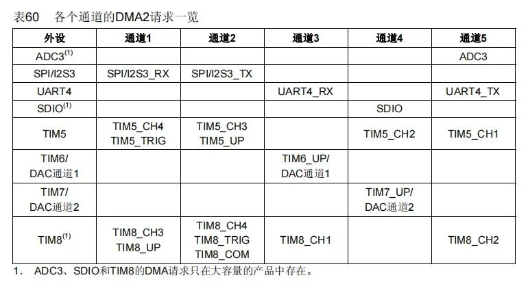
DMA2 has 5 channels
2.5 DMA and Channel Priority
Priority management is done through software and hardware:
-
Software: The priority of each channel can be set in the DMA_CCRx register, with 4 levels
Highest > High > Medium > Low
-
Hardware: If there are 2 requests and their software priorities are the same, the lower numbered channel has a higher priority than the higher numbered channel.
For example: if the software priority is the same, channel 2 takes precedence over channel 4
2.6 DMA Transfer Modes
-
DMA_Mode_Normal (Normal mode)
After a DMA data transfer is completed, stop the DMA transfer, meaning it only transfers once
-
DMA_Mode_Circular (Circular transfer mode)
When the transfer ends, the hardware automatically reloads the transfer data register for the next round of data transfer, meaning it is a multi-transfer mode
2.7 Pointer Increment Mode
The peripheral and memory pointers can automatically increment or remain constant after each transfer. When set to increment mode, the next address to be transferred will be the previous address plus the increment value.


3. Hardware Preparation
-
STM32 Core Board
This article uses the STM32F103C8T6 core board, which is very cheap, around 10 yuan on Taobao (keyword: STM32 core board), less than the price of a cup of milk tea.
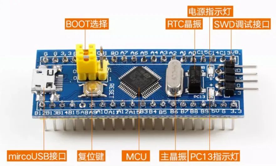
The biggest advantage of the core board is its low cost and simplicity, but the downside is that you need to build some circuits according to your needs, which requires a high degree of hands-on ability.
The recommended core board has a main control chip of STM32F103C8T6, 64K flash, 20K RAM, 4 timers, 3 serial ports, and a wealth of resources available online, making it very suitable for beginners. Highly recommended.
-
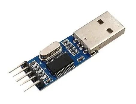
USB to TTL
This device is mainly used for debugging or downloading programs. It is also very cheap, generally around 5-8 yuan.
-
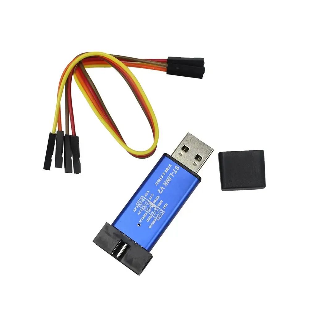
ST-Link
ST-Link is a debugging and programming tool for STM32 microcontrollers, which can communicate with the development board via SWD or JTAG interfaces. It is generally also very cheap, around seven to eight yuan.
4. Programming Practice
In this experiment, we will use serial port 1 as the log output port and serial port 2 as the receiving port for this experiment.
Therefore, we need to create a uart2 module in advance, including uart2.c and uart2.h files, and load them into the project template.

4.1 Serial Port Initialization
Everyone should be familiar with serial port initialization. The main steps are:
-
Define the serial port handle uart2_handleand callHAL_UART_Initfor initialization; -
Initialize the serial port low-level function by calling the HAL_UART_MspInitfunction.
The first step is done in the uart2.c file:
UART_HandleTypeDef uart2_handle;

void uart2_init(uint32_t baudrate)
{
    uart2_handle.Instance          = UART2_INTERFACE;              /* UART2 */
    uart2_handle.Init.BaudRate     = baudrate;                     /* Baud rate */
    uart2_handle.Init.WordLength   = UART_WORDLENGTH_8B;           /* Data bits */
    uart2_handle.Init.StopBits     = UART_STOPBITS_1;              /* Stop bits */
    uart2_handle.Init.Parity       = UART_PARITY_NONE;             /* Parity bit */
    uart2_handle.Init.Mode         = UART_MODE_TX_RX;              /* Transmission mode */
    uart2_handle.Init.HwFlowCtl    = UART_HWCONTROL_NONE;          /* No hardware flow control */
    uart2_handle.Init.OverSampling = UART_OVERSAMPLING_16;         /* Oversampling */
    HAL_UART_Init(&uart2_handle);                                  /* Enable UART2 */
}
The second step is done in the usart.c file. Actually, it can also be done in the uart2.c file, but I am lazy~
In the last two lines of code, we use __HAL_UART_ENABLE_IT() to enable the receive interrupt and idle interrupt.
void HAL_UART_MspInit(UART_HandleTypeDef *huart)
{
    GPIO_InitTypeDef gpio_init_struct;

    if (huart->Instance == USART_UX)                            /* If it is serial port 1, perform serial port 1 MSP initialization */
    {
        ....
        // Omitted serial port 1 related code
        ....
    }
    else if (huart->Instance == UART2_INTERFACE)                /* If it is UART2 */
    {
        UART2_TX_GPIO_CLK_ENABLE();                             /* Enable UART2 TX pin clock */
        UART2_RX_GPIO_CLK_ENABLE();                             /* Enable UART2 RX pin clock */
        UART2_CLK_ENABLE();                                     /* Enable UART2 clock */

        gpio_init_struct.Pin    = UART2_TX_GPIO_PIN;            /* UART2 TX pin */
        gpio_init_struct.Mode   = GPIO_MODE_AF_PP;              /* Alternate function push-pull output */
        gpio_init_struct.Pull   = GPIO_NOPULL;                  /* No pull-up or pull-down */
        gpio_init_struct.Speed  = GPIO_SPEED_FREQ_HIGH;         /* High speed */
        HAL_GPIO_Init(UART2_TX_GPIO_PORT, &gpio_init_struct);   /* Initialize UART2 TX pin */

        gpio_init_struct.Pin    = UART2_RX_GPIO_PIN;            /* UART2 RX pin */
        gpio_init_struct.Mode   = GPIO_MODE_INPUT;              /* Input */
        gpio_init_struct.Pull   = GPIO_NOPULL;                  /* No pull-up or pull-down */
        gpio_init_struct.Speed  = GPIO_SPEED_FREQ_HIGH;         /* High speed */
        HAL_GPIO_Init(UART2_RX_GPIO_PORT, &gpio_init_struct);   /* Initialize UART2 RX pin */

        HAL_NVIC_SetPriority(UART2_IRQn, 0, 0);                 /* Preempt priority 0, sub-priority 0 */
        HAL_NVIC_EnableIRQ(UART2_IRQn);                         /* Enable UART2 interrupt channel */

        __HAL_UART_ENABLE_IT(huart, UART_IT_RXNE);              /* Enable UART2 receive interrupt */
        __HAL_UART_ENABLE_IT(huart, UART_IT_IDLE);              /* Enable UART2 bus idle interrupt */
    }
}
4.2 Serial Port Interrupt Service Function
As mentioned earlier, when a serial port triggers a receive interrupt, it indicates that a character has been received, and we can place this character into the receive buffer. This process is similar to the previous article, and can refer to:
[STM32 Serial Port Receiving Variable-Length Data (Receive Interrupt + Timeout Check)]
The specific code implementation is as follows:
void UART2_IRQHandler(void)
{
    uint8_t receive_data = 0;
    if(__HAL_UART_GET_FLAG(&uart2_handle, UART_FLAG_RXNE) != RESET){    // Check if the RXNE flag is set
        if(uart2_rx_len >= sizeof(uart2_rx_buf))                        // If the number of received characters exceeds the size of the receive buffer,
            uart2_rx_len = 0;                                           // clear the receive counter
        HAL_UART_Receive(&uart2_handle, &receive_data, 1, 1000);        // Receive a character
        uart2_rx_buf[uart2_rx_len++] = receive_data;                    // Save the received character in the receive buffer
    }

    ...
    // Omitted idle interrupt code
    ...
}
When the serial port triggers an idle interrupt, it indicates that a frame of data has been received, that is, a complete data packet has been received, and we can process the received data packet (for example, print it out). The code is as follows:
void UART2_IRQHandler(void)
{
    ...
    // Omitted receive interrupt code
    ...

    if (__HAL_UART_GET_FLAG(&uart2_handle, UART_FLAG_IDLE) != RESET)    // Check if the idle interrupt flag is set
    {
        printf("recv: %s\r\n", uart2_rx_buf);                           // Print the received data
        uart2_rx_clear();
        __HAL_UART_CLEAR_IDLEFLAG(&uart2_handle);                       // Clear UART bus idle interrupt
    }
}
In the above code, be sure to call __HAL_UART_CLEAR_IDLEFLAG() to clear the UART bus idle interrupt; otherwise, the idle interrupt will remain triggered, affecting the next reception.
To determine whether a receive/idle interrupt has been received, we need to use the __HAL_UART_GET_FLAG() function; the receive interrupt checks the UART_FLAG_RXNE flag, while the idle interrupt checks the UART_FLAG_IDLE flag.
The complete code for the serial port interrupt service function is as follows (it simply combines the two parts of code above):
void uart2_rx_clear(void)
{
    memset(uart2_rx_buf, 0, sizeof(uart2_rx_buf));          // Clear the receive buffer
    uart2_rx_len = 0;                                       // Reset the receive counter
}

void UART2_IRQHandler(void)
{
    uint8_t receive_data = 0;
    if(__HAL_UART_GET_FLAG(&uart2_handle, UART_FLAG_RXNE) != RESET){    // Check if the RXNE flag is set
        if(uart2_rx_len >= sizeof(uart2_rx_buf))                        // If the number of received characters exceeds the size of the receive buffer,
            uart2_rx_len = 0;                                           // clear the receive counter
        HAL_UART_Receive(&uart2_handle, &receive_data, 1, 1000);        // Receive a character
        uart2_rx_buf[uart2_rx_len++] = receive_data;                    // Save the received character in the receive buffer
    }

    if (__HAL_UART_GET_FLAG(&uart2_handle, UART_FLAG_IDLE) != RESET)    // Check if the idle interrupt flag is set
    {
        printf("recv: %s\r\n", uart2_rx_buf);                           // Print the received data
        uart2_rx_clear();
        __HAL_UART_CLEAR_IDLEFLAG(&uart2_handle);                       // Clear UART bus idle interrupt
    }
}
The complete code for the corresponding uart2.h file is as follows:
#include <stdint.h>
#include "usart.h"

/* Pin definitions */
#define UART2_TX_GPIO_PORT           GPIOA
#define UART2_TX_GPIO_PIN            GPIO_PIN_2
#define UART2_TX_GPIO_CLK_ENABLE()   do{ __HAL_RCC_GPIOA_CLK_ENABLE(); }while(0)

#define UART2_RX_GPIO_PORT           GPIOA
#define UART2_RX_GPIO_PIN            GPIO_PIN_3
#define UART2_RX_GPIO_CLK_ENABLE()   do{ __HAL_RCC_GPIOA_CLK_ENABLE(); }while(0)

#define UART2_INTERFACE              USART2
#define UART2_IRQn                   USART2_IRQn
#define UART2_IRQHandler             USART2_IRQHandler
#define UART2_CLK_ENABLE()           do{ __HAL_RCC_USART2_CLK_ENABLE(); }while(0)

/* Error codes */
#define UART_EOK                     0   /* No error */
#define UART_ERROR                   1   /* General error */
#define UART_ETIMEOUT                2   /* Timeout error */
#define UART_EINVAL                  3   /* Parameter error */

/* UART send and receive buffer size */
#define UART2_RX_BUF_SIZE            128
#define UART2_TX_BUF_SIZE            64

void uart2_init(uint32_t baudrate);
At this point, we have actually implemented the logic code for receiving variable-length data using idle interrupts. After burning it into the board, the effect is as follows:
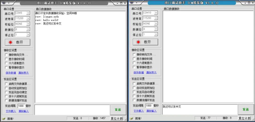
For most application scenarios, this method of handling variable-length data reception via serial communication is sufficient.
However, if the amount of data received via serial communication each time is too large, then we can bring out the DMA data mover; once data is received, it will be moved immediately without occupying CPU resources.
4.3 Adding DMA
Since we need to use the DMA peripheral, create dma.c and dma.h files in the BSP directory and load them into the project file.

In the dma.c file, what we need to do is to initialize the DMA peripheral, which essentially involves specifying where the data comes from, where it goes, and the length of the data, etc.
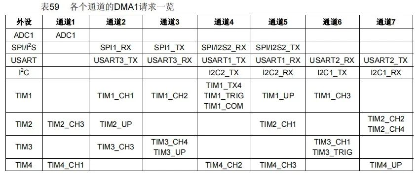
Since we are using the serial port 2 RX channel, according to the diagram below, the DMA channel used is DMA1_Channel6 (only DMA1 is available for STM32F103C8T6).
At the end of the initialization, be sure to call HAL_UART_Receive_DMA() to start DMA reception; otherwise, the DMA data mover, even if invited, will not work for you.
The detailed code is as follows:
void dma_init(void)
{
    // UART2 RX DMA configuration
    __HAL_RCC_DMA1_CLK_ENABLE();                                                /* Enable DMA1 clock */

    dma_handle.Instance = DMA1_Channel6;                                        /* The DMA channel used for USART2_RX is: DMA1_Channel6 */
    dma_handle.Init.Direction = DMA_PERIPH_TO_MEMORY;                           /* Peripheral to memory mode */
    dma_handle.Init.PeriphInc = DMA_PINC_DISABLE;                               /* Peripheral non-increment mode */
    dma_handle.Init.MemInc = DMA_MINC_ENABLE;                                   /* Memory increment mode */
    dma_handle.Init.PeriphDataAlignment = DMA_PDATAALIGN_BYTE;                  /* Peripheral data length: 8 bits */
    dma_handle.Init.MemDataAlignment = DMA_MDATAALIGN_BYTE;                     /* Memory data length: 8 bits */
    dma_handle.Init.Mode = DMA_NORMAL;                                          /* Peripheral flow control mode */
    dma_handle.Init.Priority = DMA_PRIORITY_LOW;                                /* Low priority */

    HAL_DMA_Init(&dma_handle);

    __HAL_LINKDMA(&uart2_handle, hdmarx, dma_handle);                           /* Link DMA to USART2 (send DMA) */
    HAL_UART_Receive_DMA(&uart2_handle, uart2_rx_buf, UART2_RX_BUF_SIZE);       /* Start DMA reception */
}
In the serial port interrupt service function, we can remove all the receive interrupt-related code (because we already have the DMA data mover; it is unnecessary for the CPU to transfer data character by character).
I will paste the code first and then explain it in detail.
void UART2_IRQHandler(void)
{
    if (__HAL_UART_GET_FLAG(&uart2_handle, UART_FLAG_IDLE) != RESET){           // Check if the idle flag is set
        __HAL_UART_CLEAR_IDLEFLAG(&uart2_handle);
        HAL_UART_DMAStop(&uart2_handle);                                        // Stop DMA transfer to prevent interference
        uart2_rx_len = UART2_RX_BUF_SIZE - __HAL_DMA_GET_COUNTER(&dma_handle);  // Get the length of the received data
        printf("recv: %s, recv_len: %d\r\n", uart2_rx_buf, uart2_rx_len);
        uart2_rx_clear();
        HAL_UART_Receive_DMA(&uart2_handle, uart2_rx_buf, UART2_RX_BUF_SIZE);   // Restart DMA transfer
    }
}
There are several key points in the above code that need to be explained:
-
Stop DMA transfer
When we receive an idle interrupt, the DMA has already helped us move all the data into the receive buffer. At this point, we can first stop the DMA transfer to prevent interference with subsequent operations.
-
Get the length of the received data
The __HAL_DMA_GET_COUNTER() function indicates the length of the data yet to be received by DMA. What does that mean? Suppose I need DMA to receive a data volume of 100 characters, but I have actually only received 30 characters; then the length of the data yet to be received is 70, meaning the return value of __HAL_DMA_GET_COUNTER() will be 70.
Thus, the length of the data we have already received is equal to the length of the receive buffer minus the length of the data yet to be received, which translates to code as:
uart2_rx_len = UART2_RX_BUF_SIZE - __HAL_DMA_GET_COUNTER(&dma_handle);
-
Restart DMA transfer
After processing a frame of data, we certainly need to prepare for the next frame of data reception, so we need to call HAL_UART_Receive_DMA() to restart the DMA transfer; otherwise, the data will only be received once and then stop.
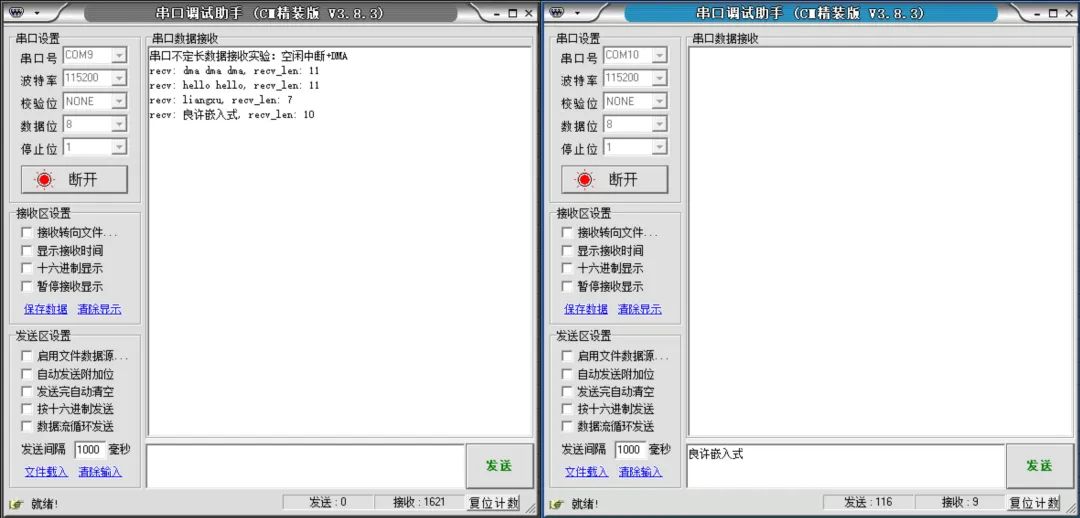
At this point, DMA has been successfully integrated. After burning it into the board, the effect is as follows:
5. Summary
STM32 serial communication is used frequently in projects, but since we do not know how much data the sender will send, receiving variable-length data via serial communication has become an urgent issue to be solved.
This article uses the idle interrupt + DMA method to solve this problem and provides a detailed tutorial, hoping to be helpful to readers.


Due to recent changes in the WeChat public account push rules, many readers have reported that they have not seen updated articles in time. According to the latest rules, it is recommended to click on “Recommended Reading, Share, Collect” more often to become a regular reader.
Recommended Reading:
-
Honda is laying off in China!
-
Thousands of people! The communication semiconductor giant is about to lay off globally
-
Official announcement! Meizu is entering the car-making industry: the first new car is coming
-
Breaking news! ByteDance is cutting its heavy business, and many companies are waiting to grab talent!
-
Breaking news! Huawei has established a new joint venture
Please click 【View】 to give the editor a chicken leg
