Understanding Analog and Digital Signals in Electronics
In the previous content, we talked about digital output driver circuits. Digital quantities are a type of boolean variable that has only two states. Here, let’s discuss analog quantities.
For a lamp, we can describe its two states—on and off—using digital quantities. Turning the lamp on means it lights up, while turning it off means it goes out. Based on this, I want to achieve control over the brightness of the lamp; the “brightness” mentioned here is an analog quantity.
For hot and cold water, we can describe the two states of hot and cool using digital quantities. However, if I want a relatively precise value to describe it, that value must be temperature; the “temperature” mentioned here is an analog quantity.
Digital quantities reflect the presence or absence, representing the relationship between 0 and 1; while analog quantities express a degree of something between 0 and 1.
How can I control the brightness of a lamp? It’s simple! By adjusting the voltage of the lamp, the higher the voltage, the brighter the lamp, and vice versa.
So how do we control a microcontroller to output an analog quantity, like controlling the brightness of an LED? Or how do we control a microcontroller to read an analog quantity, such as reading a temperature value?
Digital quantity Digital, analog quantity Analog, change Change.
Remember the line above!
Here I take the Arduino UNO/Nano/Micro as an example (the microcontrollers for these three are the same). Its main control chip is the Atmega 328P microcontroller, which has 8-bit analog output and 10-bit AD collection. Let’s first discuss the 8-bit analog output.
Analog quantities can be generated by many methods, and for Arduino, PWM is one of those methods.
Speaking of PWM, let’s first discuss two concepts—frequency and duty cycle!
The term frequency should be familiar to everyone; it refers to the number of times periodic changes occur in a unit of time, and we usually assume that unit time is 1 second.
For example, if I execute 20 times in 1 second, I can say the frequency is 20Hz, frequency = 1/unit time.
The concept of duty cycle might be a bit unfamiliar. Let me make an assumption: if a microcontroller’s pin outputs a frequency of 20Hz, how long does it take to produce a frequency of 1Hz? The answer is 1s/20 = 0.05s = 50ms!
This means that I control the microcontroller’s pin to change its high and low levels every 50ms, achieving 20 changes of high and low levels in 1 second, which is controlling the pin to output a frequency of 20Hz.
If I keep the pin at a high level for 10ms and at a low level for 10ms within 20ms, then the duty cycle at this time is 50%;
If I keep the pin at a high level for 5ms and at a low level for 15ms, then the duty cycle at this time is 25%. Therefore, the duty cycle is the ratio of the time spent at a high level to the total period in a single cycle of level change.
PWM generates a square wave signal (also sine waves, triangular waves, etc., which we will discuss later). The PWM precision of Arduino is 8 bits, so the output PWM value ranges from 0 to 255 (2^8), and the default frequency is 490Hz (generally considered to be 500Hz). Here is a reference resource:
https://www.cnblogs.com/lulipro/p/6092264.html
There are too many diagrams, and I don’t want to draw; someone else has done it quite well!
So how does PWM achieve analog output? Simply put, how does PWM control the brightness of an LED!
We previously discussed that by adjusting the voltage across the LED, we can control the brightness of the LED. So does PWM control the voltage of the microcontroller’s IO?
Yes, that can be understood this way.
No, it doesn’t work that way.
For Arduino, the output value of 0 to 255 corresponds to a duty cycle of 0 to 100%, which translates to a voltage value of 0 to 5V.
If the PWM output value of Arduino is 153, then the duty cycle at this time is 60%, meaning in 2ms (500Hz), the high level lasts 1.2ms, and the low level lasts 0.8s. The corresponding voltage value of this pin is 3V; this is PWM analog output.
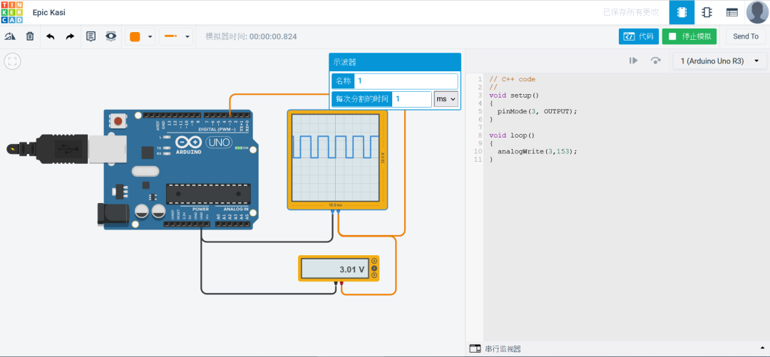
The downside of PWM is that it achieves analog output through delays, and because it uses delays, it limits its frequency to not be too high.
The minimum delay function built into Arduino is μs; 1s = 1000ms = 1000000μs, and it can only take integer values. This means that Arduino can output a square wave with a maximum duty cycle of 50% and a frequency of 500KHz.
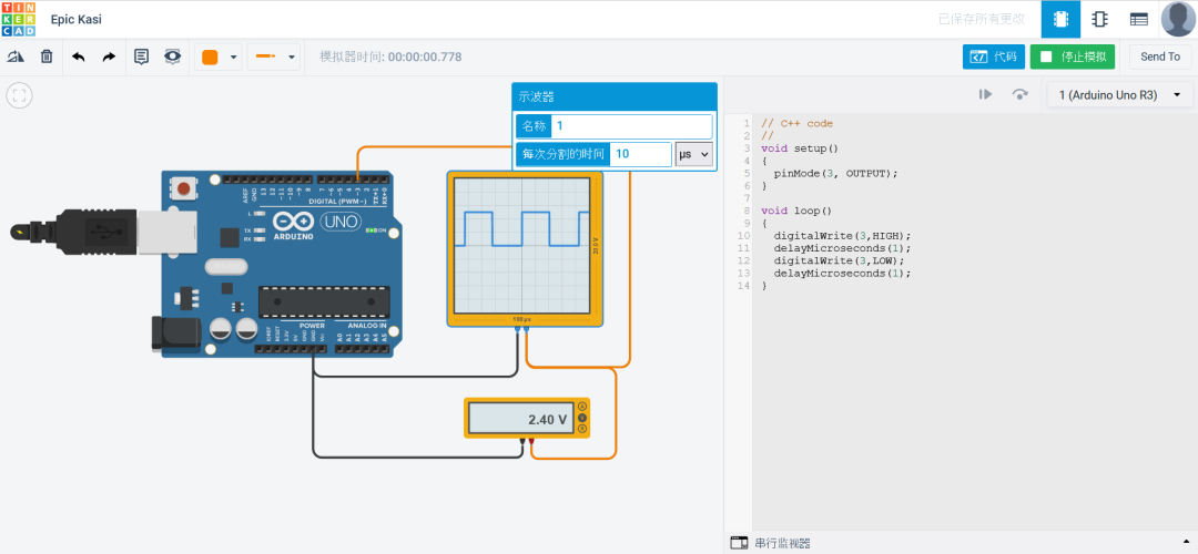
Thus, for analog output and LED brightness control, it is essentially a kind of “deception”!
The way we output analog signals through digital pins is a transformation from digital signals to analog signals, which in English is called Digital Analog Change, abbreviated as DAC.
Regarding DAC, we can often use some chips to achieve this; we will discuss this part later!

《How to Implement Robotic Arm Grasping Based on Visual Depth Reinforcement Learning》
This course mainly explains how to encapsulate your own environment in PyBullet, how to handle visual input reinforcement learning problems, and during the explanation, there will also be occasional interspersing of reinforcement learning interview questions, study methods, study materials, tool usage, sharing of experiences, and other issues that everyone may be concerned about.

(Scan the QR code to view course details)