 1. Determine the Plan and Purpose
The LHA7668 sixteen-channel acquisition module implements [flexible film pressure sensor acquisition], with the purpose of verifying the feasibility of acquisition. The requirements are as follows:
Objective: LHA7668 acquires 4 channels of film pressure sensors to verify principles and applications. 01. Build a platform with 2 large and 2 small film pressure sensors; 02. Use the test platform to acquire 4 channels of mechanical data for comparative testing; 03. Collect and analyze data; Keywords: VISA, LHA7668, serial port, STM32F4, film pressure sensor, LabVIEW. Note: High-definition images can be viewed via the mobile WeChat client; Note: For related hardware requirements, please consult "Read the original text" at the end for details.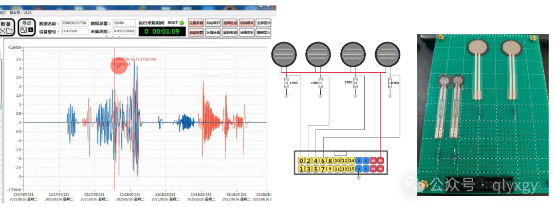 2. Optical Spectrum Acquisition DemonstrationNote: This video has been processed for accelerated playback;2. Film Pressure Sensor Principles2.1 Basic Introduction: Resistive pressure sensing sensor modules, especially those that exhibit high impedance (theoretically close to infinity) without external force, are common devices for force or pressure detection. These sensors are typically designed based on piezoresistive materials, which change their internal structure when subjected to external force, resulting in a decrease in resistance. Below is a brief introduction to the basic usage of this type of sensor and its application scenarios in mechanical hand finger force sensing.
2.2 Usage Method:
1. Select the appropriate sensor: First, choose a sensor based on your application requirements, considering pressure range, size, and sensitivity.
2. Connect the circuit: Integrate the sensor into a simple voltage divider circuit, allowing you to indirectly determine the applied pressure by measuring voltage. Generally, a fixed resistor is connected in series with the sensor to form a voltage divider. When the sensor is pressed, its resistance decreases, thereby altering the output voltage of the entire circuit.
3. Calibration: To ensure accuracy, the sensor may need to be calibrated. This includes determining the reference voltage under no pressure and the response voltage under different known weights.
4. Signal Processing: Read the analog signal through an ADC (Analog-to-Digital Converter) and convert it into a digital signal for processing by a microcontroller or computer. You may also need to write a program to parse this data and execute corresponding actions.
5. Installation and Testing: After correctly installing the sensor at the target location, begin actual testing to verify its performance meets expectations.
2.3 Application Scenarios – Mechanical Hand Finger Force Sensing
● Grip Strength Control: By installing pressure sensors in the fingers of a mechanical hand, precise control over the gripping force on held objects can be achieved. This is crucial for avoiding damage to fragile items or enhancing grip stability.
● Tactile Feedback System: With appropriate software algorithms, data collected from pressure sensors can provide information about the texture of contact surfaces, enabling robots to “feel” what materials they are touching.
● Safety Mechanism: If the mechanical hand accidentally contacts a human or other obstacles, pressure sensors set at the joints can help quickly identify this situation and immediately stop movement to prevent injury.
● Assembly Operations: In automated assembly lines, robotic arms equipped with pressure sensing capabilities can perform component assembly tasks more precisely, such as inserting electronic components.
3. Film Pressure Sensor Circuit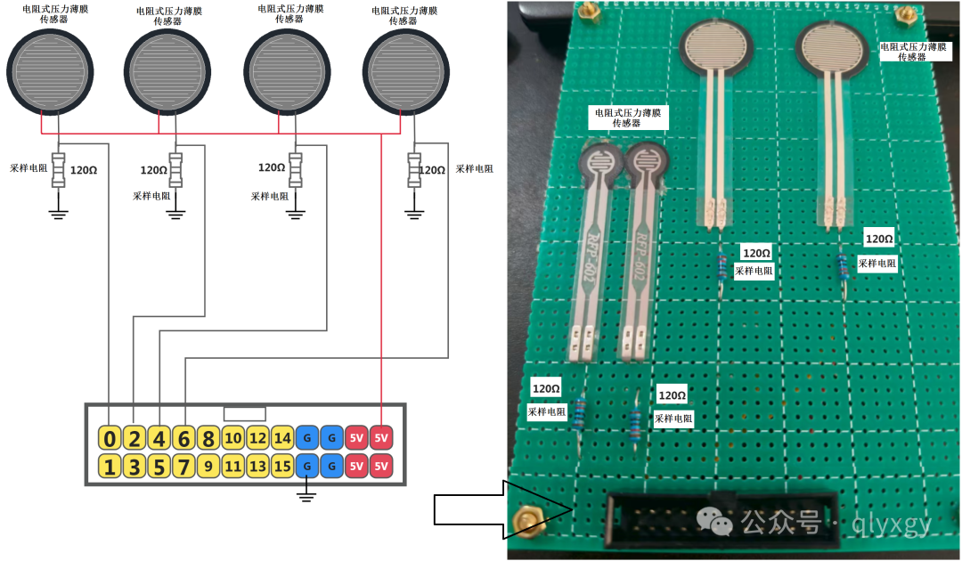
Connect the sensor to a simple voltage divider circuit using a sampling resistor to collect voltage changes, allowing you to determine the applied pressure based on the sampled voltage. It is recommended to use a precision fixed resistor in series with the sensor to form a voltage divider. When the sensor is pressed, its resistance decreases, thereby altering the output voltage of the entire circuit;
01. The sampling resistor is 120Ω, connected to ground, pressure resistance calculation method = (5V – U_sample) / (U_sample / 120);
02. The sensor’s resistance in the no-pressure state is infinite, at which point the voltage across the sampling resistor is 0V.
03. After applying pressure to the sensor, the resistance changes, and the sampling resistor needs to calculate the series current, then use voltage/current = resistance (the kx + b function is not suitable here);
4. Pressure Signal Acquisition Results
01. The above image shows a large film sensor, with the voltage feedback from the sampling resistor varying in the range up to 1000mV;
02. Series current calculation: I = voltage/current = 1V / 120Ω = 0.00833A;
03. The resistance value of the pressure sensor is calculated as: R = voltage/current = (5 – 1)V / 0.00833A = 480Ω;
04. Power consumption of the large film pressure sensor: P = U * I = 5V * 0.008333A = 0.041W;
05. Note that during the pressing of the large sensor, there may be slight changes in the parameters collected by the other two small sensors, with a voltage increase of about 1mV. The solution to this phenomenon is to replace the low-resistance collection wiring, as if there is resistance in the ground wire, for example, 0.008A flowing through 0.2Ω wiring will result in a 1.6mV change;
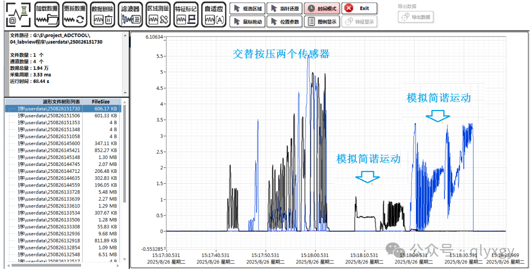
01. The above image shows a small film sensor, with the voltage feedback from the sampling resistor varying in the range of only 5.5mV;
02. Series current calculation: I = voltage/current = 0.0055V / 120Ω =0.04583mA;
03. The resistance value of the pressure sensor is calculated as:
R = voltage/current = (5 – 0.0055)V / 0.0000458A= 109.05kΩ;
04. Power consumption of the small film pressure sensor: P = U * I = 0.229mW;
05. Therefore, during the testing of the small-sized pressure film sensor, no changes were observed in the parameters collected by the other two large sensors;
06. Below are various shapes of pressure film sensors, with the basic principle being the same. Channel switching needs to be programmed, such as the logic for an 8X8 matrix using LHA7668 for acquisition: AIN0 corresponds to 8~15, …. AIN7 corresponds to AIN8~15;
5. Related Content of LHA7668
[Collection] LHA7668 Acquisition Module
[Tutorial] LHA7668_Eight-Channel Optical Signal Acquisition Testing[Tutorial] LHA7668_Battery Pack BMS Voltage Monitoring Acquisition Principles[Product] LHA7668_K-Type Thermocouple High-Precision Temperature Acquisition Testing[Notes] LHA7668 High-Precision Analog Signal Acquisition_Baseline and Noise Debugging[Tutorial] LHA7668 Sixteen-Channel Fast Acquisition Testing_Vibration Sensors6. Statement01. All images/text/designs in this tutorial are original, and copyright belongs to Qianli Youxuan Teaching Base;02. This tutorial is fortechnical sharing, applied in the educational field, and related code and technical discussions are for reference only;03. Note: High-definition images can be viewed using the mobile WeChat client;04. If you have any needs, please consult “Read the original text” at the end for details;