
Click the aboveblue text, send it to your friends circle, and share more information together😉
This power supply is for an assembled computer. When measuring the output purple and green wires, there is no voltage to ground. It is determined that the auxiliary power supply is faulty. Initially, it was thought that the auxiliary power supply’s filtering electrolytic capacitor was bulging, which would be easy to eliminate, but upon opening the cover, the capacitors appeared normal.
This power supply is very light, and there are many mounting holes on the circuit board, but components are missing. Common mode and differential mode interference suppression inductors have been omitted. It is estimated that this design is to emphasize quietness and reduce costs. Although it is equipped with a PPFC inductor, it has been shorted with jumper J0. During maintenance, care must be taken; otherwise, it may be thought that the PPFC has been removed, and the power supply is not powered on, which can lead to danger. The rectification and auxiliary power supply circuit diagram are shown in the attached figure.
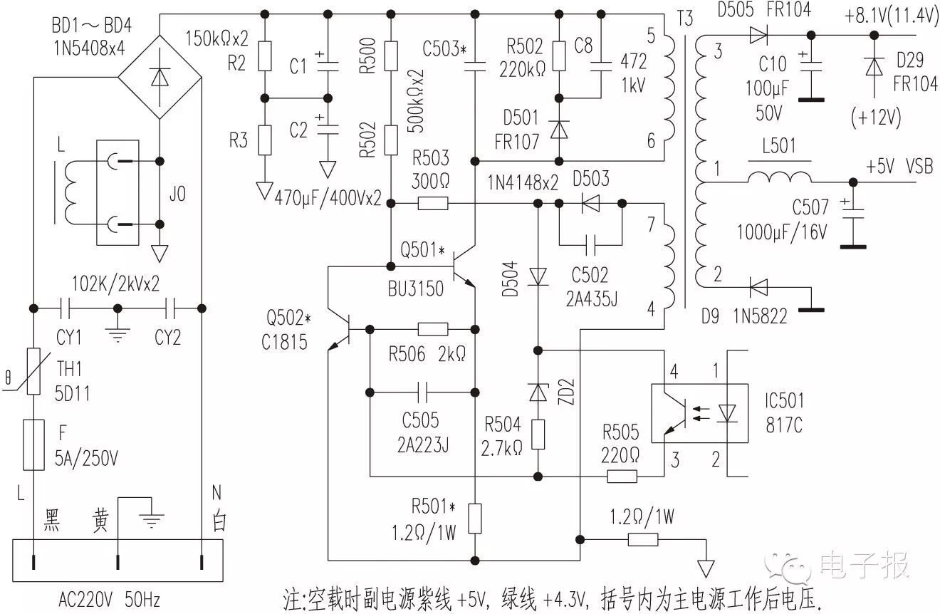
Upon careful observation of the auxiliary power supply, it was found that capacitor C503 was burnt black and crumbled at a light touch. The parameters were no longer identifiable, and the nearby capacitor C502 (2A473J) was charred, with its surface burned into a black spot.
Focus on checking the auxiliary power supply current limiting resistor R501 (1.2Ω/1W), which has changed to 2Ω. Jumper J1 is indeed a 1.2Ω/1W resistor that is open-circuit, indicating a serious short circuit in the auxiliary power supply.
Conduct a thorough inspection of the auxiliary power supply, including the output rectifier D9 (1N5832), D505 (FR104), etc., and also find that the power switch transistor Q501 (BU3150) and the adjustment transistor Q502 (C1815) are both shorted.
The burnt C503 and D502 (actually a resistor, 220kΩ), C8 (472/1kV), D501 (FR107) are mainly used to suppress the reverse peak voltage caused by the leakage inductance of transformer T3 when Q501 is turned off, to avoid breakdown of Q501 due to superimposed power supply voltage.
D502, C8, and D501 already have suppression functions, and adding another C503 feels inappropriate.
Now, abandoning C503, replace all the damaged R501, J1, Q501, Q502, and C502 with new ones. After powering on with no load, the voltage to ground of the purple and green wires is +5V and +4.3V, respectively, indicating that the auxiliary power supply is normal. Short the green wire to ground, the fan runs, and all output voltages are normal, and the main power supply is also normal. Connecting to the main unit, the microcomputer runs stably, thus the fault is eliminated.
◇ Shandong Huang Yang
Domestic Unified Publication Number: CN51-0091 Post Subscription Code: 61-75 Address: (610041) Room 2-1505, Building 7, Tianfu New Valley, No. 399, West Section of Fucheng Avenue, Chengdu Website: http://www.netdzb.com
Submission Email: [email protected] Distribution Department, Service Department: 028-65113930 Advertising Department: 028-65113931 Editorial Department: 028-65113932