The board is ready, and the MCU is soldered, but the SWD cannot connect, and the program cannot be downloaded. What should I do?
This issue seems to occur frequently, so I would like to share some recent cases I encountered.
1) Case 1: Engineer A made 5 boards, but none could connect.

After confirming that the connections were fine, I immediately thought of a power supply issue. Changing the power supply from the MCU to be powered by Jlink resolved the problem.

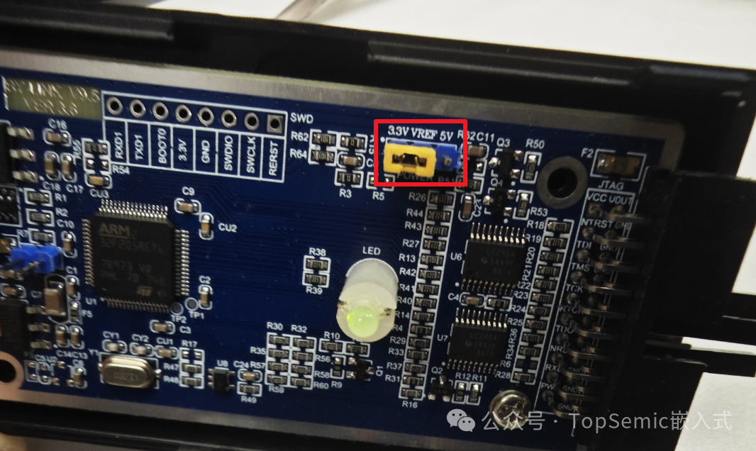
The reason for the connection failure was that the MCU was powered at 5V, while Jlink output was 3.3V, causing a level mismatch. The 3.3V could not be recognized as a high level by the 5V system, as the minimum voltage recognized as high by a 5V system is approximately 0.7*5V=3.5V. Therefore, powering the board with Jlink worked normally. Of course, the board can also connect with the MCU powered at 5V; it just requires the Jlink level to also operate at 5V. For example, this Jlink has a jumper cap inside, which by default is on the 3.3V side; moving it to the 5V side will change it to 5V level.
2) Case 2: Engineer B made 5 boards, 3 of which could connect and program normally, while 2 had connection issues.
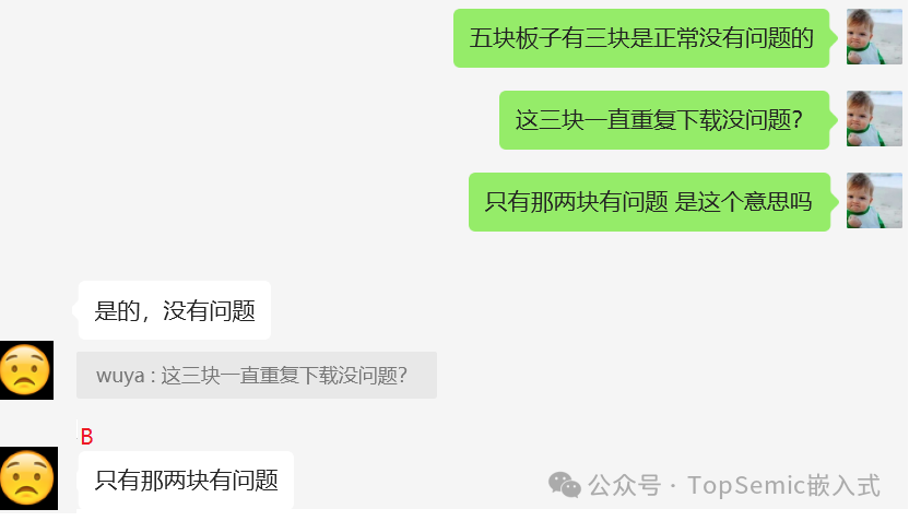
All 5 identical boards were programmed with the exact same program, but 2 had issues. Initially, I suspected that the hardware of those 2 boards was faulty, but after confirming that the hardware was also fine,

later a clue reminded me that the 2 problematic boards could connect and download the first time, but after that, they could not. Additionally, Engineer B had modified the option bytes in the program.

Details about the option bytes will not be elaborated here. This is a special Flash memory area, and modifications can be made through dedicated upper computer software or user code. Regardless of the method, it is crucial to ensure stable power supply when operating the option bytes. If there are significant power fluctuations or a reboot occurs, it may lead to a situation where the option byte area has been erased but new values have not been correctly written. Due to incomplete writing, before the subsequent option byte loading, the original value and the complement value may not match, which could force a modification to other values, resulting in a change in RDP level and subsequently causing SWD connection issues.
The engineer modified the option bytes at the initial stage of the program, and the contact between the fixture probe and the board during programming may have been unstable, leading to the aforementioned issues.
The countermeasure is to wait for the power to stabilize before operating the option bytes, for example, by adding a short delay in the program to ensure stability before executing the option byte operation. Since there is also an external serial port on the board, data can be received through this serial port during production testing, or the option bytes can be operated after receiving data through the serial port, as the power will be stable at that time. In summary, avoid operating the option bytes during the unstable power period caused by poor contact during programming. Additionally, when operating option bytes in the program, it is important to execute it only once and not modify the option bytes every time after a reset.
3) Case 3: Engineer C had no issues with previous projects but could not connect with a new project.

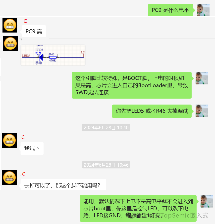
This issue was caused by pulling the MCU BOOT pin high, which needs to be considered during hardware design.
There are also other situations where SWD cannot connect:
1) The MCU has entered a low-power state. When entering low power, the SWD clock stops, making it impossible to connect. There are two ways to solve this issue: a) During debugging, add a few seconds delay before entering low power in the program, so that there is enough time to connect after the next power-up or reset. b) Connect the reset pin of the debugger to the MCU’s Reset pin, allowing a hard reset to connect before entering low power.
2) SWD has been repurposed for other functions. When there are not enough pins, the SWD interface may be used for other functions; in this case, it is also recommended to add some delays in the program.
3) In addition to the BOOT pin mentioned above, some MCUs also have an NMI pin. If this pin is low during power reset, it will enter the NMI interrupt, causing SWD to fail to connect normally.
4) During hot-plugging in debugging, the SWD interface may be damaged. It is advisable to avoid hot-plugging as much as possible; connect the cables first, then power on. Additionally, try to avoid situations where SWD is powered on before the MCU.
If none of the above situations apply, another possibility is that the chip was soldered incorrectly, which I have also encountered.

So next time you encounter an MCU SWD connection issue, prioritize checking the above situations.
Follow us:
Scan the code to join the embedded development group: