
Brushless Motor Speed Measurement and Speed Control
-
Introduction to Brushless Motor
-
The speed feedback closed-loop control system of a brushless motor is a basic feedback control system characterized by three fundamental features, which are the basic rules of feedback control. All basic feedback control systems, without additional regulators, adhere to this rule.
-
1. The controlled quantity has static error
From the schematic diagram of the brushless motor, it is clear that due to the use of a proportional amplifier, the open-loop gain of the closed-loop system increases, resulting in better steady-state performance. As long as the amplifier set is merely a proportional amplifier, the steady-state speed difference can only be reduced but not eliminated. This type of speed control system is called a static error speed control system, which relies on the deviation of the controlled quantity for control.
2. Resistance to disturbances, compliance with given values
The feedback control system of the brushless motor exhibits excellent disturbance resistance, effectively suppressing disturbances in the forward path surrounded by negative feedback, but it must comply with changes in given values.
Disturbances, apart from the given signal, refer to all factors acting on each link of the control system that cause changes in output quantities, known as “disturbance effects”.
3. The system’s accuracy depends on the precision of the given and feedback detection
The precision of the given value determines the output precision of the brushless motor. If the power supply generating the given voltage fluctuates, the feedback control system cannot distinguish between normal adjustments of the given voltage and undesirable voltage fluctuations. Therefore, a high-precision speed control system must have a more stable power supply with higher precision.
Brushless Direct Current (BLDC) motors are a rapidly proliferating type of motor, with numerous applications in mobile robotics. Here, we will describe some common issues related to brushless DC motors.
(1) Working Principle
First, let’s take a look at the working principle of the brushless motor. The following diagram demonstrates a three-pole, two-magnet, inner rotor brushless motor.
Brushless motors are not traditional DC motors; although they are powered by DC batteries, they convert to three-phase alternating current through brushless electronic speed controllers. As shown in the diagram, brushless motors lack carbon brushes, and unlike brushed motors, the magnets are part of the rotor.
The open-loop control system is the simplest control system, where only rotor position sensors provide feedback information about the rotor’s position, ensuring that the motor’s commutation is always synchronized with the rotor’s position. The motor’s speed and current are determined by the mechanical characteristics of the motor and the load being driven. If there are changes in voltage or load, the motor’s speed will also change, making it uncontrollable.
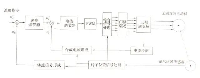
Common dual closed-loop control systems for speed and current can achieve better control performance, allowing for speed adjustment or constant speed control within a certain range. They require speed feedback and current feedback information, so speed sensors and current sensors are typically set up.
The working principle of this system: first, the speed set value un* is compared with the speed feedback value un to obtain the speed difference, which is adjusted by the PI (Proportional and Integral) speed regulator. The output becomes the current loop’s set value un*, which is compared with the current feedback value ui. The current difference is then amplified and corrected by the current regulator, and the adjusted signal is converted into corresponding PWM pulse widths in the PWM circuit. This is then combined with the rotor position signal to generate the required phase PWM control signals. These PWM control signals are sent to the base (or gate) of the driving circuit, which drives the three-phase inverter bridge circuit, activating the corresponding power switching devices with an appropriate PWM duty cycle to drive the motor windings. Additionally, this system uses rotor position feedback information to sample the current sensor signal, forming a synthetic current signal ui that represents the motor’s torque and ensuring that the back electromotive force and phase current’s phase remain consistent. Furthermore, by processing the output signal from the Hall position sensor, the speed feedback signal un is obtained. The system commonly includes protections against overvoltage, undervoltage, overcurrent, overheating, overspeed, and I2t (winding overheating) anomalies. The speed command is typically an analog voltage of 0 to 10V, corresponding to speeds from 0 to full speed. New systems also use digital signals for speed commands. The dual closed-loop control system allows the brushless DC motor to automatically adjust under varying voltage, load, or external disturbances, enabling its speed to track and reproduce the requirements of the speed command.
2. STM32 Brushless Motor Wheel Speed Measurement
Specific code implementation:
Below is an example with one motor:
External interrupt configuration code:
// Motor Hall external interrupt configuration function
void Hall_EXIT_Config(GPIO_TypeDef* GPIOx,uint16_t GPIO_Pin)
{
GPIO_InitTypeDef GPIO_InitStructure;
EXTI_InitTypeDef EXTI_InitStructure;
NVIC_InitTypeDef NVIC_InitStructure;
u8 EXTI_IRQn;
uint8_t GPIO_PortSource,GPIO_PinSource;
uint32_t EXTI_Line;
// External interrupt requires enabling AFIO clock
RCC_APB2PeriphClockCmd(RCC_APB2Periph_AFIO,ENABLE);
// Enable GPIO clock
if(GPIOx == GPIOA) RCC_APB2PeriphClockCmd(RCC_APB2Periph_GPIOA, ENABLE),GPIO_PortSource = GPIO_PortSourceGPIOA;
else if(GPIOx == GPIOB) RCC_APB2PeriphClockCmd(RCC_APB2Periph_GPIOB, ENABLE),GPIO_PortSource = GPIO_PortSourceGPIOB;
else if(GPIOx == GPIOC) RCC_APB2PeriphClockCmd(RCC_APB2Periph_GPIOC, ENABLE),GPIO_PortSource = GPIO_PortSourceGPIOC;
else if(GPIOx == GPIOD) RCC_APB2PeriphClockCmd(RCC_APB2Periph_GPIOD, ENABLE),GPIO_PortSource = GPIO_PortSourceGPIOD;
else if(GPIOx == GPIOE) RCC_APB2PeriphClockCmd(RCC_APB2Periph_GPIOE, ENABLE),GPIO_PortSource = GPIO_PortSourceGPIOE;
else if(GPIOx == GPIOF) RCC_APB2PeriphClockCmd(RCC_APB2Periph_GPIOF, ENABLE),GPIO_PortSource = GPIO_PortSourceGPIOF;
else if(GPIOx == GPIOG) RCC_APB2PeriphClockCmd(RCC_APB2Periph_GPIOG, ENABLE),GPIO_PortSource = GPIO_PortSourceGPIOG;
// Select interrupt line and interrupt service function
if(GPIO_Pin == GPIO_Pin_0) GPIO_PinSource = GPIO_PinSource0, EXTI_Line = EXTI_Line0, EXTI_IRQn = EXTI0_IRQn;
else if(GPIO_Pin == GPIO_Pin_1) GPIO_PinSource = GPIO_PinSource1, EXTI_Line = EXTI_Line1, EXTI_IRQn = EXTI1_IRQn;
else if(GPIO_Pin == GPIO_Pin_2) GPIO_PinSource = GPIO_PinSource2, EXTI_Line = EXTI_Line2, EXTI_IRQn = EXTI2_IRQn;
else if(GPIO_Pin == GPIO_Pin_3) GPIO_PinSource = GPIO_PinSource3, EXTI_Line = EXTI_Line3, EXTI_IRQn = EXTI3_IRQn;
else if(GPIO_Pin == GPIO_Pin_4) GPIO_PinSource = GPIO_PinSource4, EXTI_Line = EXTI_Line4, EXTI_IRQn = EXTI4_IRQn;
else if(GPIO_Pin == GPIO_Pin_5) GPIO_PinSource = GPIO_PinSource5, EXTI_Line = EXTI_Line5, EXTI_IRQn = EXTI9_5_IRQn;
else if(GPIO_Pin == GPIO_Pin_6) GPIO_PinSource = GPIO_PinSource6, EXTI_Line = EXTI_Line6, EXTI_IRQn = EXTI9_5_IRQn;
else if(GPIO_Pin == GPIO_Pin_7) GPIO_PinSource = GPIO_PinSource7, EXTI_Line = EXTI_Line7, EXTI_IRQn = EXTI9_5_IRQn;
else if(GPIO_Pin == GPIO_Pin_8) GPIO_PinSource = GPIO_PinSource8, EXTI_Line = EXTI_Line8, EXTI_IRQn = EXTI9_5_IRQn;
else if(GPIO_Pin == GPIO_Pin_9) GPIO_PinSource = GPIO_PinSource9, EXTI_Line = EXTI_Line9, EXTI_IRQn = EXTI9_5_IRQn;
else if(GPIO_Pin == GPIO_Pin_10) GPIO_PinSource = GPIO_PinSource10,EXTI_Line = EXTI_Line10,EXTI_IRQn = EXTI15_10_IRQn;
else if(GPIO_Pin == GPIO_Pin_11) GPIO_PinSource = GPIO_PinSource11,EXTI_Line = EXTI_Line11,EXTI_IRQn = EXTI15_10_IRQn;
else if(GPIO_Pin == GPIO_Pin_12) GPIO_PinSource = GPIO_PinSource12,EXTI_Line = EXTI_Line12,EXTI_IRQn = EXTI15_10_IRQn;
else if(GPIO_Pin == GPIO_Pin_13) GPIO_PinSource = GPIO_PinSource13,EXTI_Line = EXTI_Line13,EXTI_IRQn = EXTI15_10_IRQn;
else if(GPIO_Pin == GPIO_Pin_14) GPIO_PinSource = GPIO_PinSource14,EXTI_Line = EXTI_Line14,EXTI_IRQn = EXTI15_10_IRQn;
else if(GPIO_Pin == GPIO_Pin_15) GPIO_PinSource = GPIO_PinSource15,EXTI_Line = EXTI_Line15,EXTI_IRQn = EXTI15_10_IRQn;
// Pin initialization
GPIO_InitStructure.GPIO_Pin = GPIO_Pin; // Port configuration
GPIO_InitStructure.GPIO_Mode = GPIO_Mode_IPU; // Pull-up input
GPIO_Init(GPIOx, &GPIO_InitStructure); // Initialize GPIO based on set parameters
GPIO_EXTILineConfig(GPIO_PortSource,GPIO_PinSource);
EXTI_InitStructure.EXTI_Line = EXTI_Line;
EXTI_InitStructure.EXTI_Mode = EXTI_Mode_Interrupt;
EXTI_InitStructure.EXTI_Trigger = EXTI_Trigger_Rising_Falling; // Trigger on both rising and falling edges
EXTI_InitStructure.EXTI_LineCmd = ENABLE;
EXTI_Init(&EXTI_InitStructure); // Initialize external interrupt registers based on EXTI_InitStruct parameters
NVIC_InitStructure.NVIC_IRQChannel = EXTI_IRQn; // Enable the external interrupt channel where the button is located
NVIC_InitStructure.NVIC_IRQChannelPreemptionPriority = 0x02;// Preemption priority 2,
NVIC_InitStructure.NVIC_IRQChannelSubPriority = 0x01; // Sub-priority 1
NVIC_InitStructure.NVIC_IRQChannelCmd = ENABLE; // Enable the external interrupt channel
NVIC_Init(&NVIC_InitStructure);
}
Timer configuration code:
void TIM4Init(u16 Timing,u16 Divis)
{
TIM_TimeBaseInitTypeDef TIM_TimeBaseStructure;
NVIC_InitTypeDef NVIC_InitStructure;
RCC_APB1PeriphClockCmd(RCC_APB1Periph_TIM4, ENABLE);
TIM_TimeBaseStructure.TIM_Period = Timing;// Counting value
TIM_TimeBaseStructure.TIM_Prescaler = Divis; // Prescaler value
TIM_TimeBaseStructure.TIM_ClockDivision = 0; // No division, 72MHz clock frequency
TIM_TimeBaseStructure.TIM_CounterMode = TIM_CounterMode_Up;// Up counting mode
TIM_TimeBaseInit(TIM4, &TIM_TimeBaseStructure);
TIM_ITConfig(TIM4,TIM_IT_Update,ENABLE); // Enable timer 3 update interrupt
TIM_Cmd(TIM4, ENABLE);// Turn on TIM4
NVIC_InitStructure.NVIC_IRQChannel=TIM4_IRQn; // Timer 4 interrupt
NVIC_InitStructure.NVIC_IRQChannelPreemptionPriority=0x03; // Preemption priority 3
NVIC_InitStructure.NVIC_IRQChannelSubPriority=0x01; // Sub-priority 1
NVIC_InitStructure.NVIC_IRQChannelCmd = ENABLE;
NVIC_Init(&NVIC_InitStructure);
}
Left wheel three-phase Hall processing function:
// Left wheel three-phase Hall processing function
void left_hall_deal(TIM_TypeDef* TIMx,char *motor_state,char *hall_state_last,char *hall_state_now,unsigned short int *count,double *speed)
{
if(*motor_state==2){ // If in a stationary state, the previous count is zero regardless of its value
*count=0; // Count is zero
TIM_SetCounter(TIMx,0); // Clear timer
}
else // If not in a stationary state
{
*count=TIM_GetCounter(TIMx);// Record the timer’s count value between two pulses
TIM_SetCounter(TIMx,0);// Clear the timer counter, starting a new count
}
if(*count==0){ // If the timer counter count is zero, speed is zero
*speed=0;
}
else if(*count>10) // Prevent re-entering the interrupt, as the motor’s speed will not reach 16077.1mm/s = 16.0071m/s
{
//0.5/311.0=0.00160771704 The actual distance traveled by the wheel between two pulses, this depends on individual wheel conditions
//0.001607717/(1/100000.0)=160.771704 The speed measured between two pulses is 160.771704m/s; here, 100000 is because the timer’s counting frequency is 100k, meaning each count takes 1/100000s.
// The more counts, the slower the speed; if the count exceeds 10000, it is considered stationary; 10000 can be modified, which is the overflow value of the counter
*speed=1000*160.771704/(double)*count;
*count=0; // Speed calculation completed; clear count buffer for next count
}
// A simple way to obtain the combination state of the three Hall sensors
*hall_state_now=(GPIO_ReadInputDataBit(GPIOE,GPIO_Pin_10)<<2)|(GPIO_ReadInputDataBit(GPIOE,GPIO_Pin_11)<<1)|(GPIO_ReadInputDataBit(GPIOE,GPIO_Pin_12));
if(*count>10||*count==0)
{
switch(*hall_state_last)
{// Reverse Forward No Change
case 1:if(*hall_state_now!=3){*motor_state=1;}else if(*hall_state_now==1){}else{*motor_state=0;};break;
case 3:if(*hall_state_now!=2){*motor_state=1;}else if(*hall_state_now==3){}else{*motor_state=0;};break;
case 2:if(*hall_state_now!=6){*motor_state=1;}else if(*hall_state_now==2){}else{*motor_state=0;};break;
case 6:if(*hall_state_now!=4){*motor_state=1;}else if(*hall_state_now==6){}else{*motor_state=0;};break;
case 4:if(*hall_state_now!=5){*motor_state=1;}else if(*hall_state_now==4){}else{*motor_state=0;};break;
case 5:if(*hall_state_now!=1){*motor_state=1;}else if(*hall_state_now==5){}else{*motor_state=0;};break;
default:break;
}
}
if(*motor_state==1) // Based on the motor’s direction, assign speed sign
*speed=-*speed;
*hall_state_last=*hall_state_now;// Record the last Hall combination state for the next judgment of motor direction
}
Left wheel three-phase Hall interrupt service function:
//L
void EXTI15_10_IRQHandler(void)
{
if(EXTI_GetITStatus(EXTI_Line10)==SET){
EXTI_ClearITPendingBit(EXTI_Line10); // Clear pending bit for LINE10
}
if(EXTI_GetITStatus(EXTI_Line11)==SET){
EXTI_ClearITPendingBit(EXTI_Line11); // Clear pending bit for LINE11
}
if(EXTI_GetITStatus(EXTI_Line12)==SET){
EXTI_ClearITPendingBit(EXTI_Line12); // Clear pending bit for LINE12
}
left_hall_deal(TIM4,&left_motor_state,&left_hall_state_last,&left_hall_state_now,&left_count,&left_speed);
}
Timer interrupt service function:
void TIM4_IRQHandler(void)
{
if(TIM_GetITStatus(TIM4,TIM_IT_Update)==SET) // Overflow interrupt
{
TIM_ClearITPendingBit(TIM4,TIM_IT_Update); // Clear interrupt flag
left_motor_state=2;// Motor stationary; also needs to measure the minimum speed of the motor based on specific conditions
left_count=0;
left_speed=0;
}
}
Main function:
//=================================Header Files===================================
#include “sys.h”
#include “delay.h”
#include “exti.h”
#include “tim4.h”
/*===================================================================
Program Function: Speed Measurement Testing of Brushless DC Motor
===================================================================*/
int main(void)
{
GPIO_PinRemapConfig(GPIO_Remap_SWJ_Disable,ENABLE);
GPIO_PinRemapConfig(GPIO_Remap_SWJ_JTAGDisable,ENABLE);// Disable JTAG, enable SWD
NVIC_PriorityGroupConfig(2); //===== Set interrupt grouping
delay_init(); //===== Initialize delay function
Hall_EXIT_Config(GPIOE,GPIO_Pin_10); //LA Hall external interrupt detection
Hall_EXIT_Config(GPIOE,GPIO_Pin_11); //LB
Hall_EXIT_Config(GPIOE,GPIO_Pin_12); //LC
TIM4Init(10000-1,720-1); //===== For speed measurement
while(1)
{
}
}
//===================================END======================================