
Today, someone in the group shouted that there was a power short circuit on the board, and they had almost removed all the components, yet the short circuit still persisted. This feeling of helplessness, exhaustion, and frustration resonates with many!
|
|
|
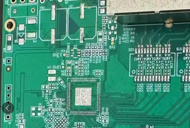
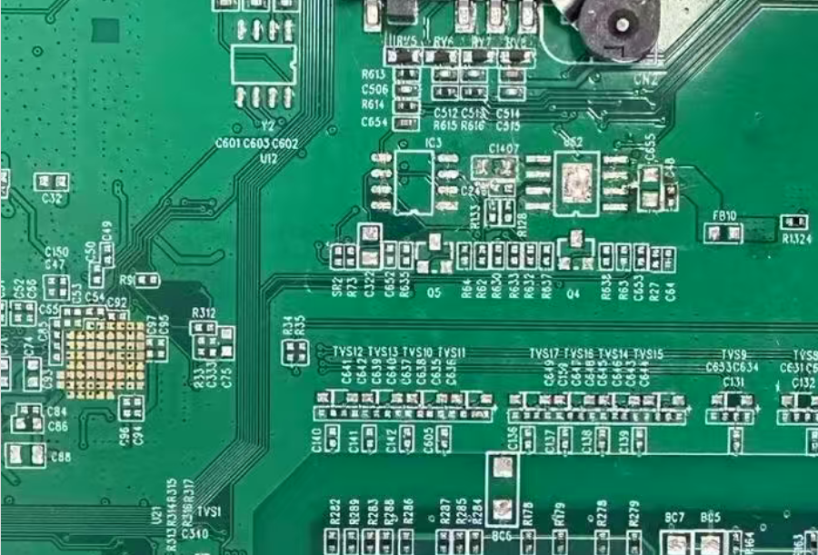
Engineers working with hardware and those involved in manufacturing must have encountered this situation numerous times! SMT soldered circuit boards, especially during manual soldering of prototypes, are more prone to such issues.
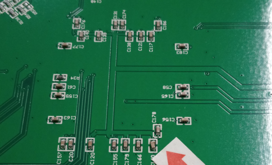
As we all know, circuit boards, especially those that are slightly complex, have a large number of capacitors used for power supply, ranging from dozens to hundreds, along with many chips connected to power systems like 3.3V and 1.8V. A careless mistake, such as a 0402 or 0603 capacitor touching solder, can lead to a short circuit, or a densely pin-packed chip can also short out due to solder. At this point, troubleshooting becomes a headache.
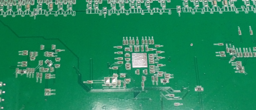
When we encounter a short circuit in a major power supply on a circuit board, how should we systematically troubleshoot it? I would like to share my thoughts based on my experience:
1.Quick Visual Inspection
Upon discovering the issue, the quickest method is to visually inspect the components on the circuit board, especially densely pin-packed chips and the surfaces of MLCC capacitors. Based on your understanding of the circuit, quickly identify potential areas and scan for any obvious short circuits.
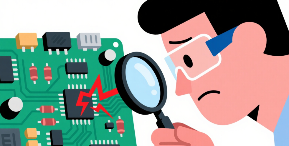
This method is only suitable for a preliminary experience-based overview to determine the possible range, as it cannot pinpoint specific related components or pins; it’s somewhat like searching for a needle in a haystack.

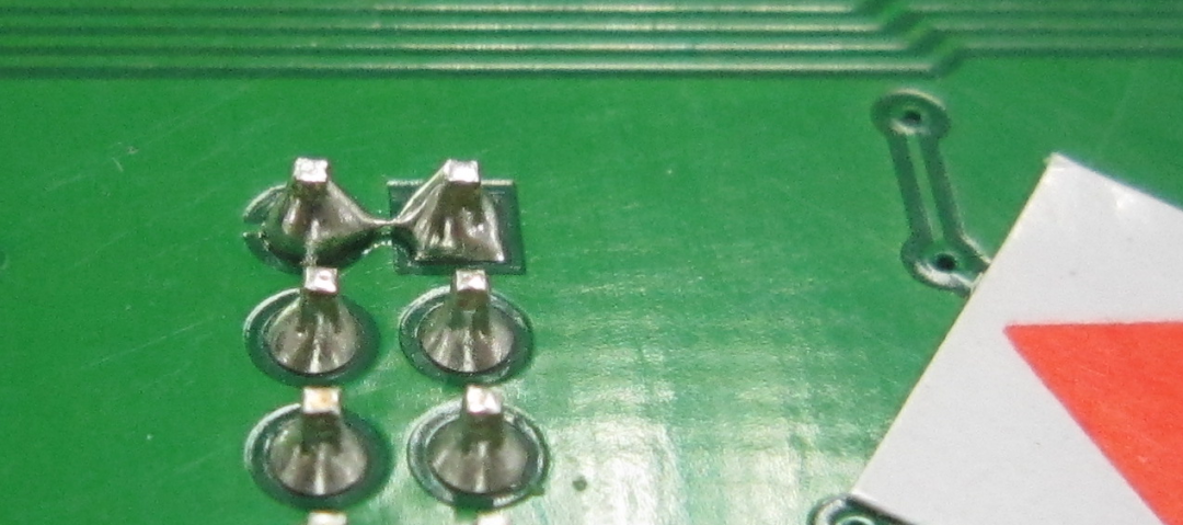
Visual short circuit solder reminder: Pay special attention to the sides and even the bottom of the surface-mounted capacitors for solder connections; sometimes, solder debris or accidentally pulling solder wire during repairs can cause short circuits.
2. Open the PCB File to Locate the Exact Range
If the initial visual inspection does not reveal the problem, then open the PCB file to locate all components (capacitors and chips) involved in the shorted power supply.
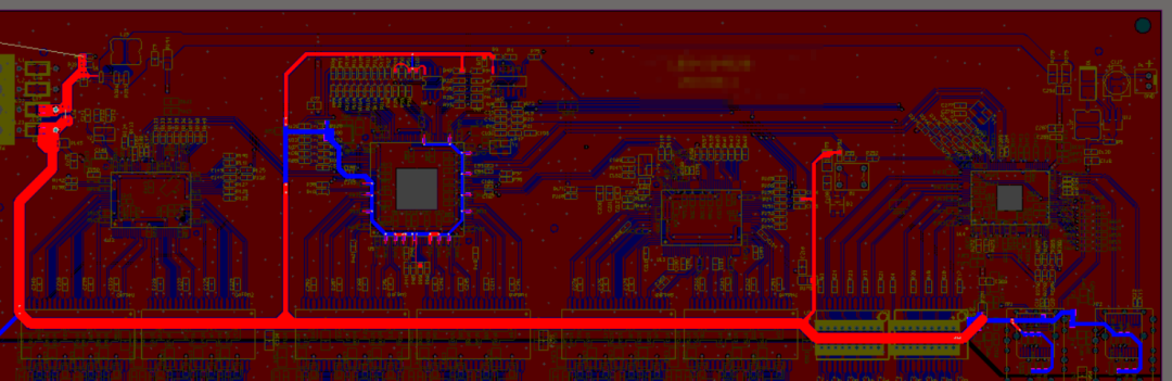
If it’s a 3.3V power short circuit, then directly highlight all networks connected to the 3.3V power supply in the software. This narrows the range from the entire circuit board to specific areas.
In the PCB software, all chip pins and capacitor pins related to the power network will be displayed one by one, and the next step is to systematically check each one.
Start from left to right and check carefully; if nothing is still visible, then cut the traces.
3. Cut the “Main Traces” to Gradually Narrow Down the Range for Inspection
If the entire range cannot be identified, then cutting traces to narrow the range is necessary (this should only be done for very large ranges).
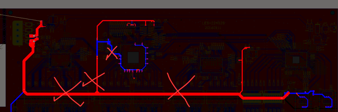
As shown in the figure, cut each segment of the relevant main and branch traces, and measure for short circuits to determine which side is shorted. Then continue to open each segment along the side of the short circuit until the final point is located (during this process, visual inspection and desoldering remain the primary methods; if still unclear, continue cutting).
At this point, you may find that if there are specific designs for troubleshooting faults in the main or branch lines, it will be very convenient (for example, adding a 0-ohm resistor in the branch can be easily desoldered).
4. Increase Current to Directly Burn the Short Circuit
This method is not highly recommended, but if there’s no other option, it can be tried.
The principle is to directly apply a DC power supply and gradually increase the short circuit current. For example, start with a short circuit current of only 2A, then increase to 3A, 5A. If the short circuit point is a very thin metal wire or solder debris, it may not take long before it melts due to the increased current and time, thus eliminating the short circuit.
However, this method may not reveal which location is shorted, and if the short circuit is severe, increasing the current may not melt it either. Therefore, this method is only suitable for very minor short circuits.
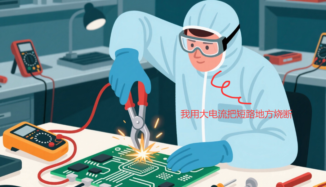
Additionally, when using the short circuit method to burn out, it is essential to assess whether it will affect other circuits, and the duration must be controlled; otherwise, it may create hidden dangers in areas that were previously fine.
5. Pay Attention to the “Leakage” Issue of Pads
As mentioned by friends in the group, after almost removing all components, why is there still a short circuit?
At this point, we need to consider whether the short circuit is due to the PCB itself?
Normally, the PCBs provided by the board factory are electrically tested, so the probability of a short circuit when they reach the customer is almost zero. However, it is not impossible; it could be due to a missed test or confusion after testing, but overall, the probability is low.
The most likely cause is still due to manufacturing process issues at the PCB factory, leading to poor solder mask application, resulting in leakage at the edges of the traces and pads.

The so-called “leakage” issue is primarily caused by the board factory not controlling the manufacturing process well, as the solder mask on the edges of the traces was not applied correctly. This is usually fine before wave soldering or reflow soldering, but after soldering, if a bit of solder sticks, it can easily cause networks that should not be connected to connect.
|
|
|

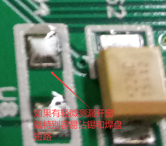
Since I do not have case images on hand, I used the above images to illustrate.
Moreover, this issue is very subtle; it may not be easily resolved with a soldering iron and may require cutting traces.
6. Apply Flux on Suspected Components like Capacitors
This method involves applying some flux on the surface of a bunch of capacitors. When the temperature rises, the flux on the capacitor will start to melt, allowing for judgment based on this.
7. Use Infrared Thermal Imaging to Find Temperature Anomalies
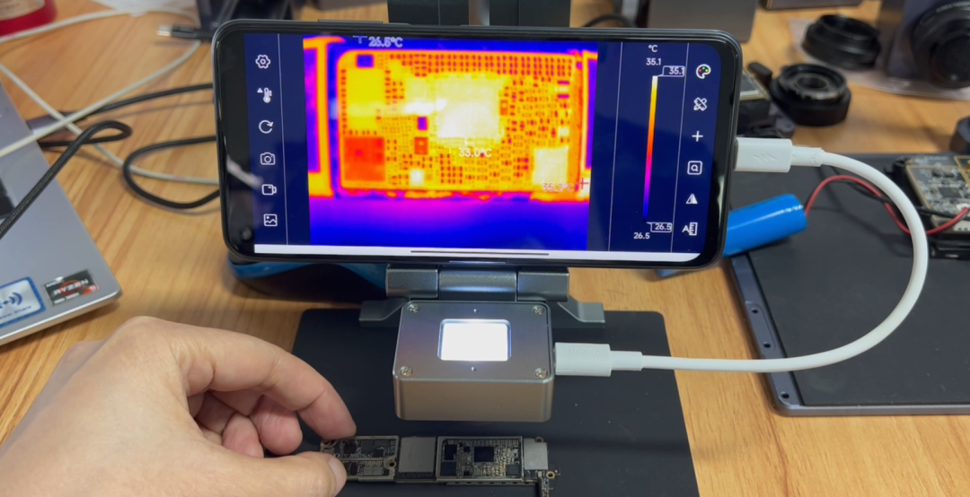
When there is a short circuit on the circuit board, the current increases, leading to heat generation. By measuring the temperature with infrared thermal imaging, you can observe areas that are different from the surrounding ones. This principle can be used to directly find hot spots with infrared equipment.
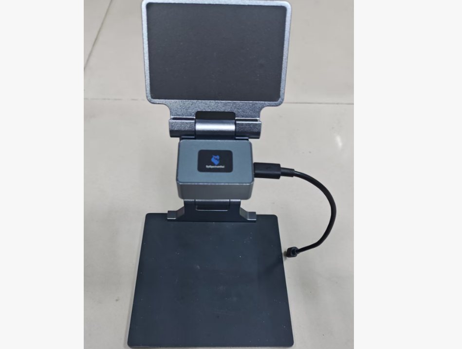
As I write this, I suddenly recall a thermal analysis tool for circuit board repair that a manufacturer in Shenzhen let me try last year. This tool is quite helpful for identifying abnormal high temperatures.
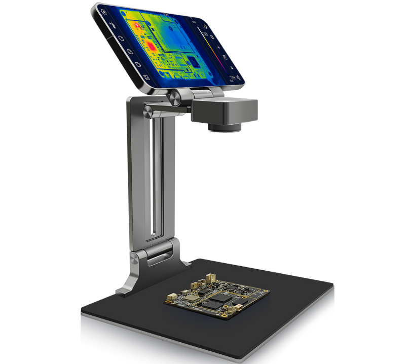


This repair tool is very useful for solving some difficult problems. The display can be connected via a mobile phone, and with powerful software, it not only helps to find obvious temperature anomalies to locate short circuits but can also be used to assess temperature dissipation issues on the circuit board.
Do you have any other methods for locating short circuits on circuit boards?
Related Articles:
Still too young! Do you really think that providing GERBER data to the board factory will ensure 100% compliance with your specifications?
If compared to the Fire Rabbit toy, how many points would you give it? – Disassembling the Blue Treasure Toy