Smart Control Education
Focusing on the training of skilled personnel in the intelligent manufacturing industry

Hello everyone! Let’s learn a small piece of industrial control knowledge every day. I am Xiao Zhi, and I am here again! I believe everyone has gained some understanding of the touchscreen standards through yesterday’s learning. Today, Xiao Zhi will continue to guide everyone in learning about the layout of touchscreen standards (internal standards of foreign companies). Let’s get started!
User Management
The requirements for the user management interface are as follows:
a.The permission descriptions are shown in the table below:
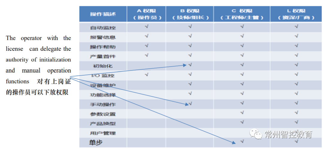
b.The user management interface mainly includes functions such as adding new users, deleting users, changing index account passwords, changing user permissions, and setting user logout times. It also provides permission descriptions for different levels of users. Logged-in users can manage users with relatively lower permission levels.
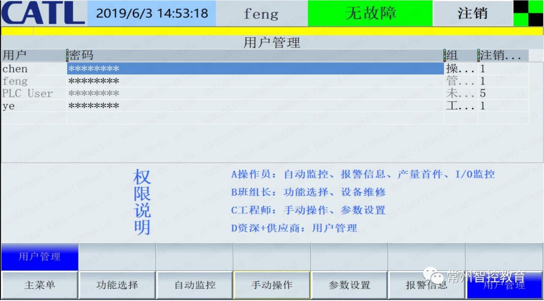
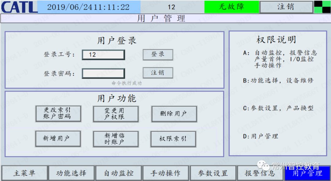
c.The user management interface is shown in the figure below:
(Siemens Touchscreen)
(Weinview Touchscreen)
If the user does not operate within the set time, the system will automatically log out the current user and return to the login screen.
The automatic operation monitoring requires real-time monitoring of the following items: equipment operating status, operating parameters, cycle monitoring, wear parts of tools and fixtures, I/O monitoring, etc. The three-level interface buttons are placed at the top of the secondary interface, aligned neatly, and can reserve empty buttons, as shown in the figure below. Since the functions of equipment in each process are different, please communicate and confirm the automatic monitoring screen in advance with the relevant engineers. The three-level interface returns to the secondary interface by clicking the function button on the secondary interface.
a.The operating parameter monitoring interface requires displaying all the process parameters that need to be collected and monitored, including production information, formula parameters, etc.
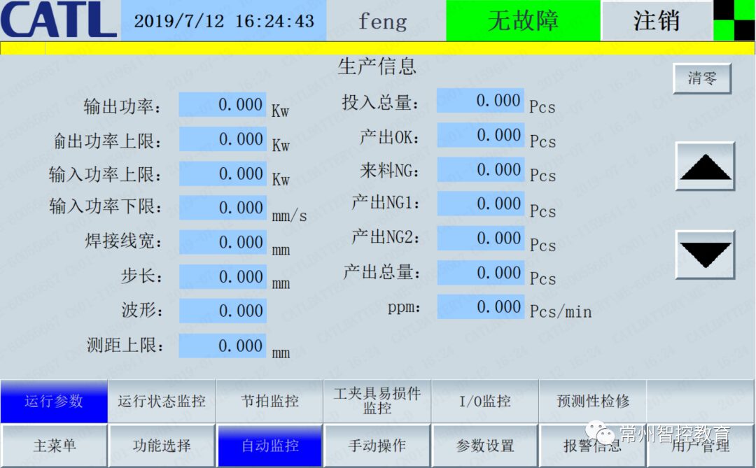
(Production Information)
Include monitoring values of formula parameters. The monitoring values on this page are parameters for formula changeovers, facilitating operators to monitor changeover parameters after the changeover, as well as monitoring the device’s center value to check the operational status of the equipment.
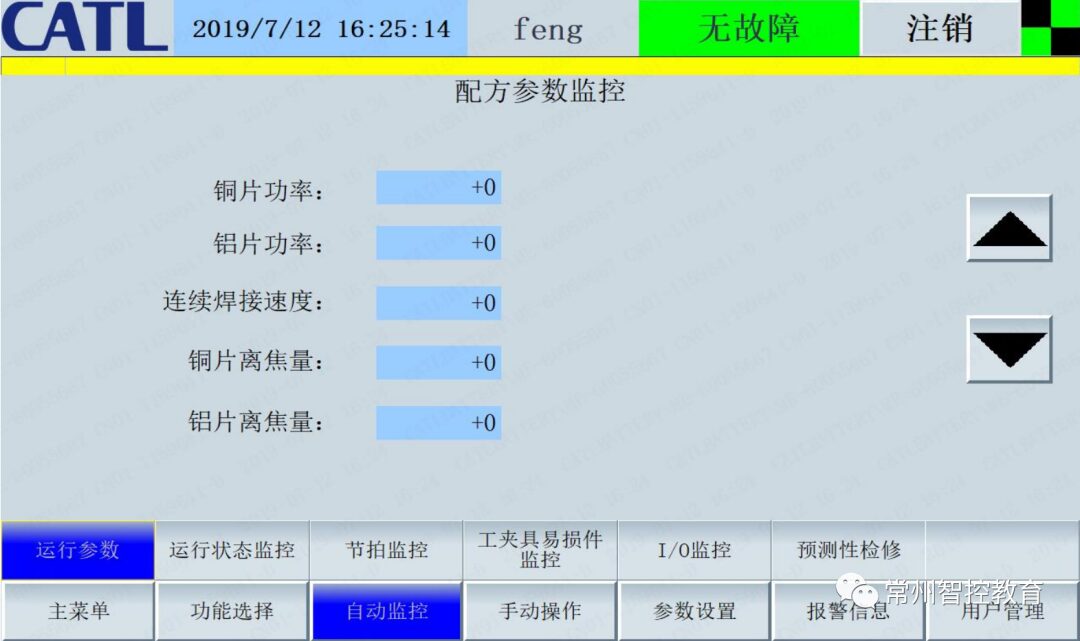
(Formula Parameter Monitoring)
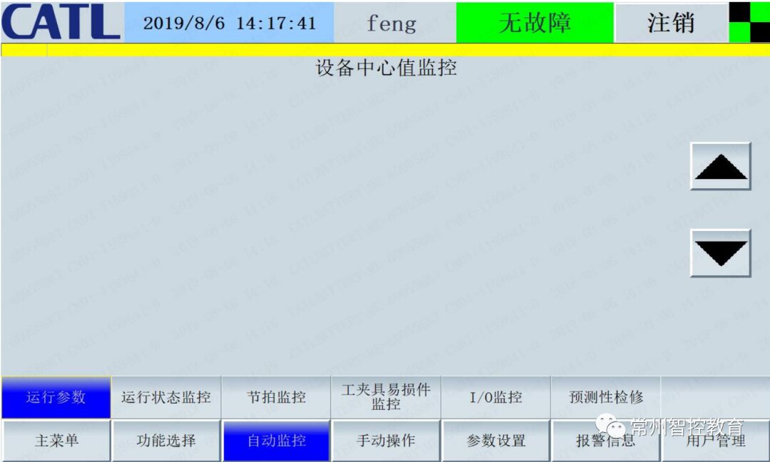
(Device Center Value Monitoring)
b.Operating Status
Reasonable segmentation based on detailed equipment automatic operation processes, detailed breakdown of individual process statuses, with real-time changes for each action status. It allows monitoring of work processes, and the corresponding area can change color when an alarm occurs. Clicking on the colored area will lead to a schematic diagram of the area for troubleshooting. (For alarm illustrations, please refer to the explanations on the real-time alarm side).
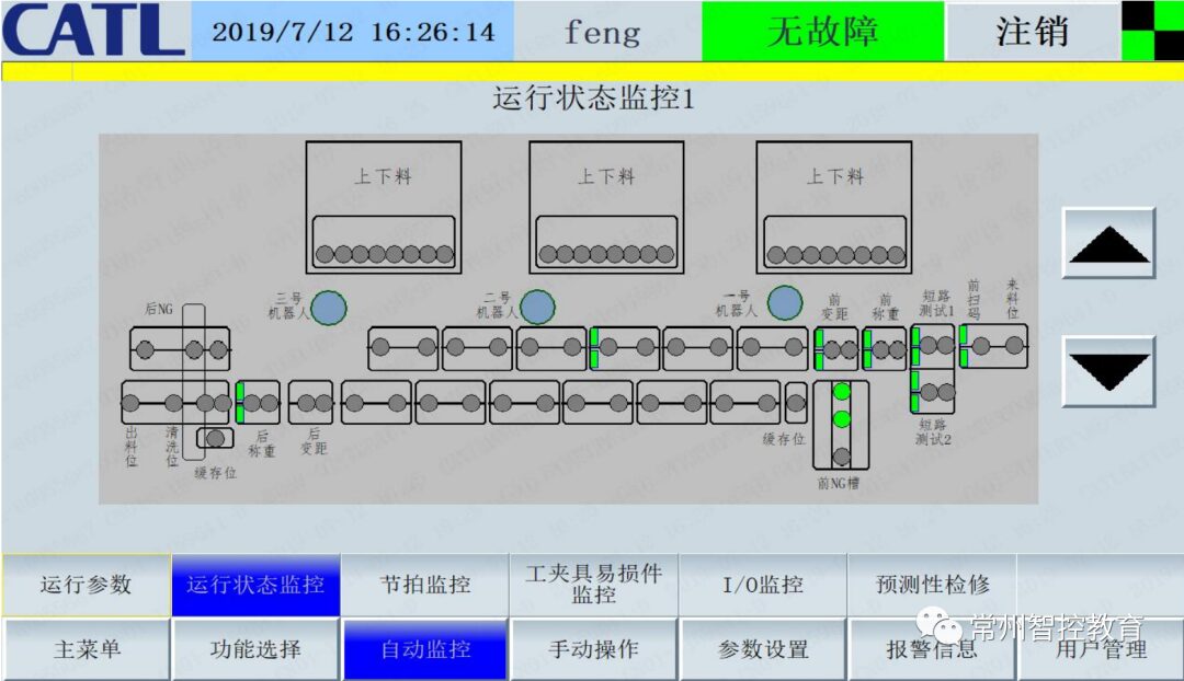
(Operating Status Monitoring)
c.Cycle Monitoring
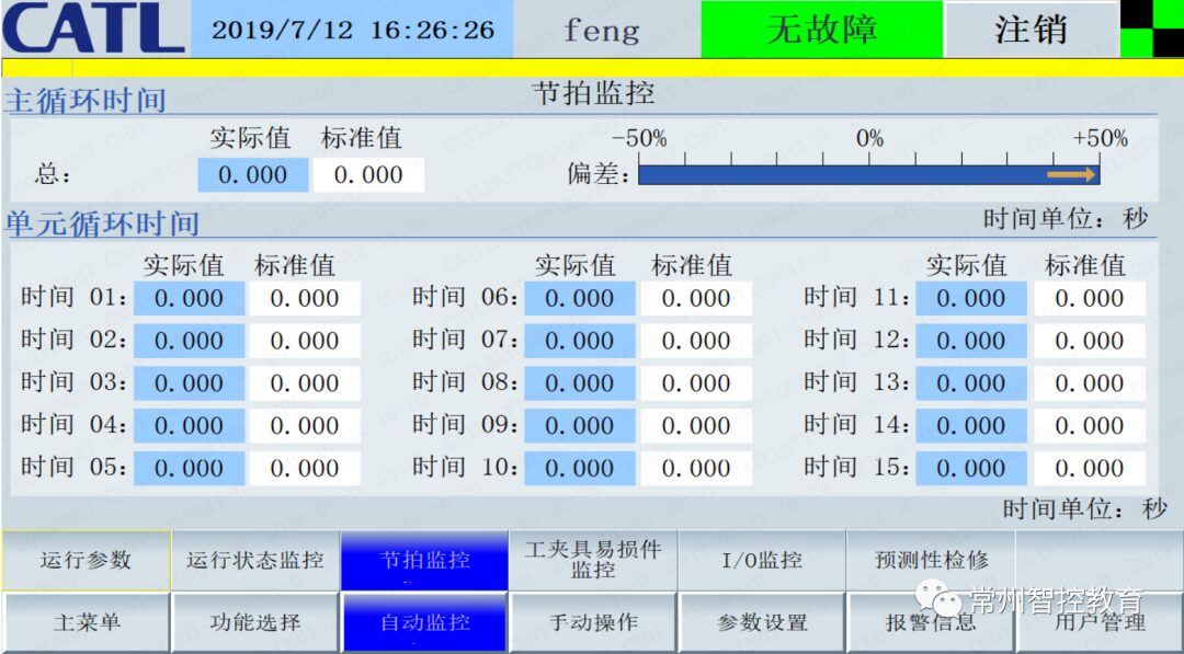
(Cycle Monitoring)
d.Monitoring of Wear Parts of Tools and Fixtures
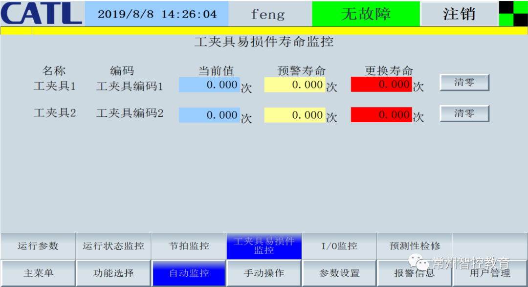
(Monitoring of Wear Parts of Tools and Fixtures)
Monitor the lifespan of wear parts and tools, including coding, current values, warning lifespan, and replacement lifespan. The reset function requires engineer-level permissions or above. When reaching the warning lifespan and replacement lifespan, alarm prompts will appear. The former will not stop equipment operation, while the latter will stop equipment operation (wear parts such as welding heads, cutters, sealing components, etc., with the list of wear parts provided by the supplier, and Company C will review).
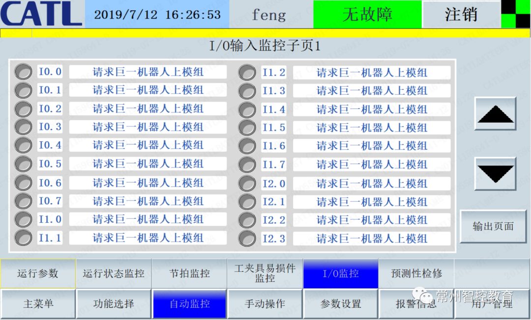
e.I/O Monitoring
1. It is required to layout strictly according to the electrical schematic to facilitate quick reference to the schematic for finding line numbers and other maintenance work;
2. Distinguish between local I/O and remote I/O for the I/O module at least, differentiating input and output I/O;
3. I/O content includes I/O points, position codes (reference alarm position codes), and specific electrical components monitored by I/O (e.g., double-sided clamp cylinder extending/retracting, test channel 5 indicating OK, etc.);
4. I/O monitoring indicator lights gray when disconnected and green when connected;
5. The I/O monitoring interface is distributed by module, and the upper and lower sub-interfaces can be switched using the up and down arrows on the right. The interface naming is uniform and clearly identifiable, e.g., feeding position I/O monitoring;
The I/O monitoring screen is shown in the figure below:
f.Predictive Maintenance and Status Monitoring
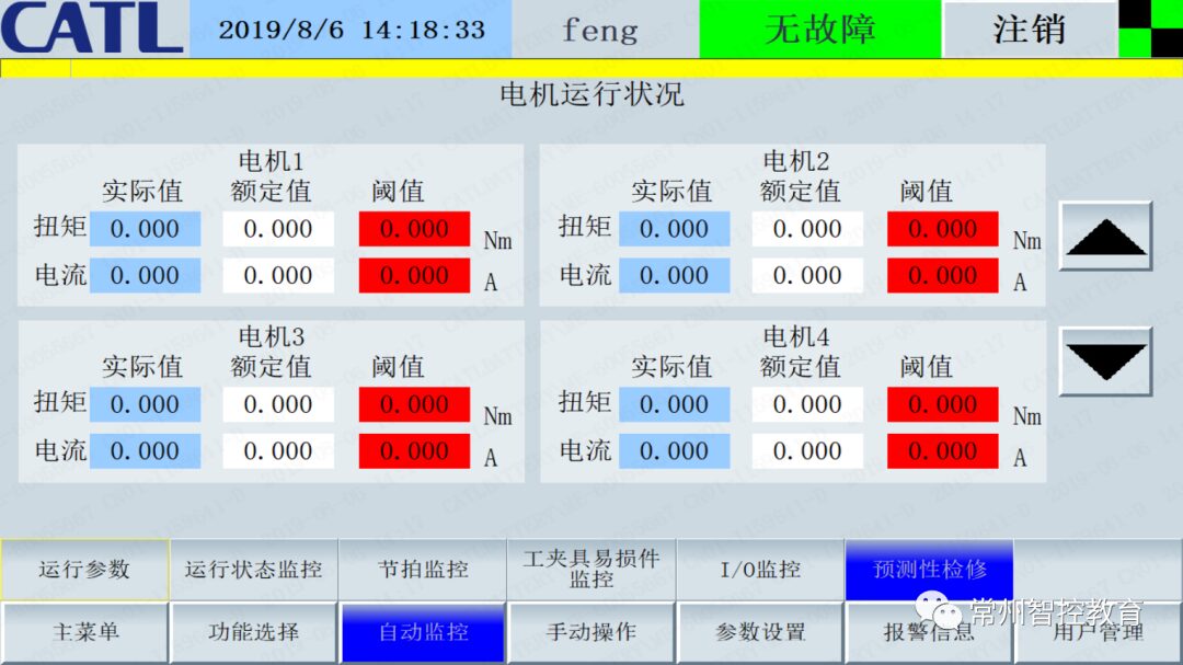
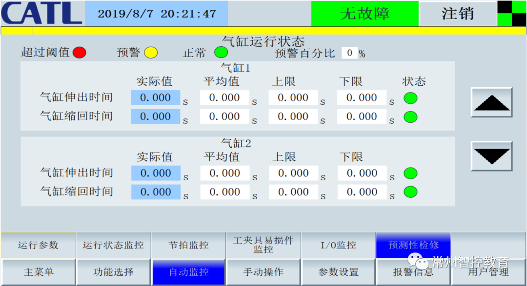
1. The predictive maintenance and monitoring interface is divided into two parts: motor operating status and cylinder operating status. The motor operating status mainly collects the actual values of motor current and torque, and compares them with the rated values of torque and current. If they exceed a certain range, the system will issue an alarm action and stop the currently alarming motor, prompting technicians to check! The cylinder operating status mainly displays the actual moving time of the cylinder, average time after N moves, threshold range for movement, and warning percentage. When the actual time exceeds the threshold range, the status light will display red. When the actual time is between the threshold and warning values (warning value = average value ± average value * warning percentage), the status light displays yellow, and the device emits a prompt signal; when within the warning value range, the status light displays green, indicating normal status.
2. The predictive maintenance and monitoring interface is divided into two parts: motor operating status and cylinder operating status. The motor operating status mainly collects the actual values of motor current and torque, and compares them with the rated values of torque and current. If they exceed a certain range, the system will issue an alarm action and stop the currently alarming motor, prompting technicians to check! The cylinder operating status mainly displays the actual moving time of the cylinder, average time after N moves, threshold range for movement, and warning percentage. When the actual time exceeds the threshold range, the status light will display red. When the actual time is between the threshold and warning values (warning value = average value ± average value * warning percentage), the status light displays yellow, and the device emits a prompt signal; when within the warning value range, the status light displays green, indicating normal status.
Today, I will share this much. There are still many screen standards that will be continuously updated. I hope everyone studies this touchscreen framework well; it is all experience we have accumulated over a long time. If you like it, please follow Smart Control and give a thumbs up and share!