Today, LED lights have become the mainstream for lighting, with very few households using incandescent bulbs. The main advantage is that LED lights are more energy-efficient, consuming over 70% less power than incandescent bulbs for the same light output.LED lights have a longer lifespan compared to incandescent bulbs. Anyone who has used incandescent bulbs knows that the tungsten filament burns out after a short period. Statistics show that the average lifespan of an incandescent bulb is about 1000 hours, which means if used for 10 hours a day, it lasts only about 100 days, or a little over 3 months. In contrast, LED lights can last up to 100,000 hours, theoretically lasting up to 10 years. Some may argue that they don’t last that long and fail after a few months. This is just a theoretical value; the actual lifespan is related to the design of the LED driver circuit. Many manufacturers simplify the design to save costs, leading to unstable current and voltage, which reduces the lifespan of LED lights.
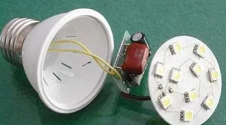
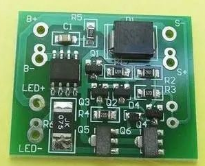
Household LED light beads are low-voltage, low-current devices, typically operating at around 3V and 20mA. Lighting the LED beads requires an LED driver circuit, so a small circuit board inside the LED fixture is the LED driver circuit board.Common Functions of LED Driver Circuit Boards1. Capacitive and resistive step-down, rectification, and filtering simple LED driver circuit board.This type of circuit board has a simple structure, saving costs; however, the circuit is unreliable, with a high failure rate, leading to a shorter lifespan for the LED lights.
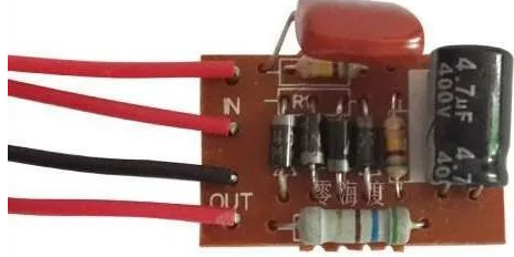
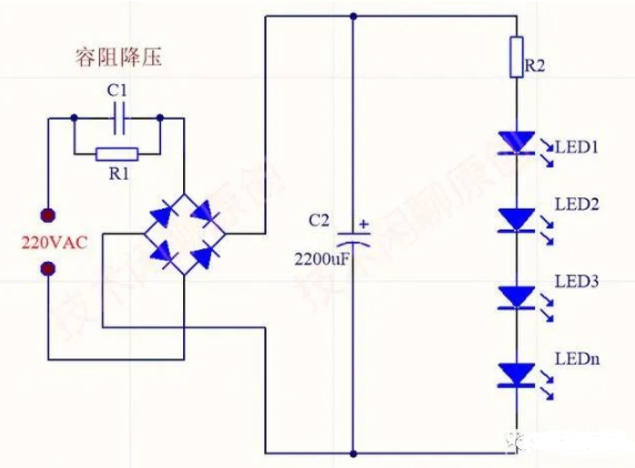
The diagram below shows the capacitive step-down LED circuit. The 220V AC is stepped down using capacitive resistance, then rectified and filtered to obtain a DC voltage that directly drives the LED beads.
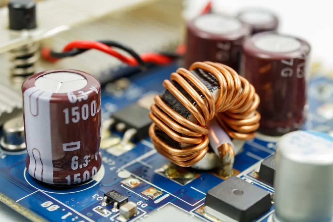
2. LED Constant Voltage Driver Board.The diagram below shows the LED constant voltage driver board, whose circuit principle is similar to a switch-mode power supply, directly driving the LED beads with the constant voltage output from the switch-mode power supply.
The principle of the switch-mode power supply is shown in the diagram below. The 220V AC is converted into approximately 310V high-voltage DC through a rectifier bridge, then PWM modulation causes the switch tube to turn on/off at high speed, forming an alternating current signal that is output as AC voltage through a high-frequency transformer, and then rectified to output DC voltage.3. LED Constant Current Source Driver Board.Using a constant current source to drive LEDs yields the best results, providing uniform brightness and reducing the risk of damage, thus extending lifespan.
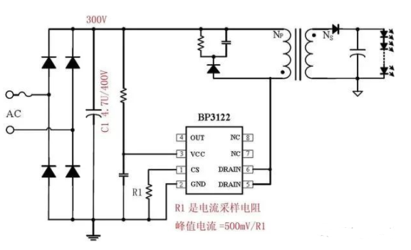
For example, the diagram below shows the principle of a constant current source driving LED lights, designed using the BP3122 constant current source driver chip, where R1 is the current sensing resistor, and changing the value of R1 can change the load current.
Conclusion: Lighting the LED beads requires an LED driver circuit. Generally, LED driver circuits include constant voltage, constant current, and PWM driving, which is the function of the small circuit board in LED lights.END

Scan to Join Power Supply Technology WeChat Group▼Previous Highlights▼Why is it said that operational amplifiers should be used sparingly as comparators in design? Not discussing principles, only applications of operational amplifiers (recommended to bookmark) Real image analysis of 7 classic operational amplifier circuits This analogy of operational amplifiers is simply brilliant! 24 classic circuits formed by operational amplifier LM358! Circuit analysis: Constant current source circuit composed of operational amplifiers and transistors Differential operational amplifier formula derivation, extremely detailed!