In automotive applications, the CAN bus transceiver interface circuit often includes a component known as a choke. This component is typically reserved for placement on the PCB, but in the final product, it may or may not be installed. What is the purpose of this component? Is it really necessary?
1. What is a choke?
A choke, also known as acurrent-limiting inductor, is primarily made of a core and inductance, which is why it is also referred to as a core inductor. Its structure consists of wire wound around a core to enhance the inductance.
Inductors have the characteristic of “allowing DC while blocking AC,” so a choke is an electronic component that uses inductive properties to suppress alternating current.
We know that the inductive reactanceXL is proportional to frequency and inductance, that is, XL=2πfL. This means that as the frequency of the signal increases and the inductance value increases, its reactance becomes larger, thus enhancing its blocking effect.
Therefore, chokes can be classified by operating frequency into high-frequency chokes and low-frequency chokes. High-frequency chokes have a smaller inductance value and are used to block high-frequency signal transmission; low-frequency chokes can have inductance values of several tens of henries and are commonly used for power filtering and audio circuits.
In addition to classification by signal frequency, chokes can also be categorized by the type of interference signal into differential mode chokes and common mode chokes. Due to the nature of chokes being inductive, they are also referred to as differential mode inductors and common mode inductors.
Common differential mode inductors are wound with one winding on a single magnetic core, resulting in two pins;
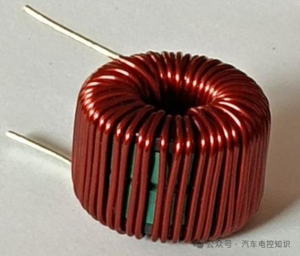
Differential mode inductor
In contrast, common mode inductors are wound with two windings on a single magnetic core, resulting in four pins.
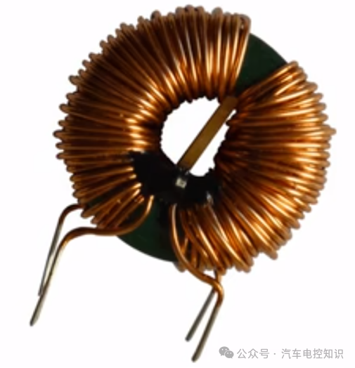
Common mode inductor
Why does a differential mode inductor have two pins while a common mode inductor has four? This is related to the types of signals they suppress. Differential mode inductors are used to suppress differential mode interference signals, while common mode inductors are used to suppress common mode interference signals.
2. Differential Mode Interference vs. Common Mode Interference
Many communication buses in vehicles, such as CAN, LVDS, USB, Ethernet, etc., use differential signaling due to the long transmission distances.
Taking the CAN bus as an example, the transmission lines are primarily CANH and CANL, and the final transmission and reception are based on the voltage difference between these two lines. For instance, when both CANH and CANL are at 2.5V, their difference is 0; when CANH=3.5V and CANL=1.5V, their difference is 2V.
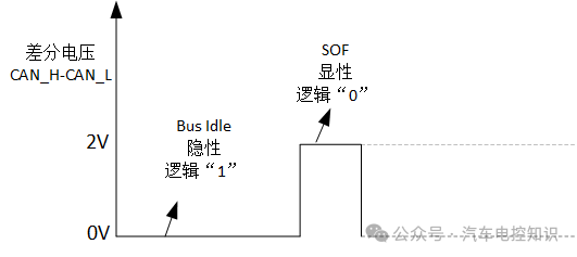
CAN’s dominant and recessive levels
In the differential transmission of the CAN bus, CANH and the external load (receiving end, termination resistor, etc.) can form a signal loop with CANL, and differential mode interference occurs between these two transmission lines.
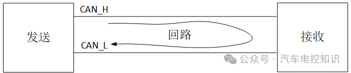
Differential mode interference signal loop
The current of the differential mode interference signal flows out from one line and into the other, so the amplitude (magnitude) of the signal on both lines is the same, while the phase (direction) is opposite.
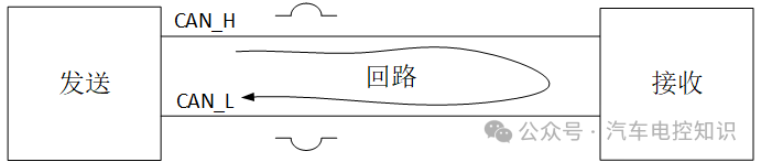
Differential mode interference signal waveform
Note that this differential mode interference signal is an “interference” signal, not the normal differential signal intended for transmission. Typically, motors, switch-mode power supplies, and thyristors operating on the same line will generate differential mode interference.
In the circuit, in addition to the differential loop, there is also a ground loop, where the two transmission lines can also form a loop with the ground, and common mode interference arises from these two transmission lines and the ground.
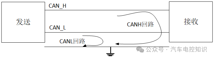
Common mode interference loop
The current of the common mode interference signal flows out from both lines, both flowing into the ground, so the waveform characteristics of the common mode interference signal are that the phases (directions) are the same, and the amplitudes (magnitudes) may be the same or different.
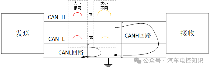
Common mode interference signal waveform
Lightning, electric arcs, radio stations, or other high-power radiation devices can easily generate common mode interference on nearby wires. Additionally, wires passing near strong magnetic field radiation sources (such as switch-mode power supplies) can also easily produce common mode interference.
In practical applications, common mode interference often has a large amplitude, high frequency, and can radiate through wires, resulting in significant interference.
In contrast, differential mode interference has a smaller amplitude, lower frequency, and causes less interference, which can sometimes be addressed with simple methods such as filtering capacitors. Therefore, common mode inductors are more commonly used in circuits.
3. Common Mode Inductor
A common mode inductor, also known as a common mode choke, is wound with the same number of turns in opposite directions on the upper and lower halves of a magnetic core. The choke used in our CAN bus is a common mode choke.
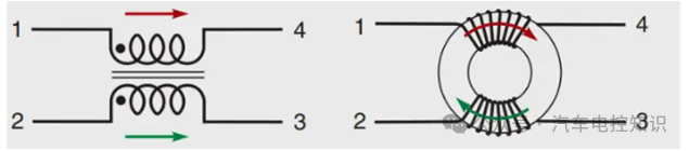
Common mode inductor
When common mode current enters, according to the right-hand rule in Ampere’s law, if you hold the energized solenoid with your right hand, with your fingers pointing in the direction of the current, then your thumb points to the N pole of the energized solenoid.
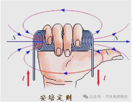
Ampere’s Law2 – Right-Hand Rule
Thus, the right side of the upper half of the magnetic core is the N pole, the left side is the S pole, with external magnetic field lines going from right to left and internal magnetic field lines going from left to right.
The left side of the lower half is the N pole, the right side is the S pole, with external magnetic field lines going from left to left and internal magnetic field lines going from right to left. Therefore, the internal magnetic field lines of the two coils are in the same direction, both clockwise, and the magnetic flux will add up.
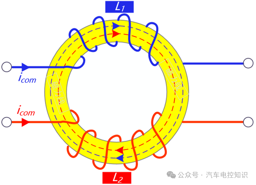
The direction of the magnetic field lines generated when common mode signals enter is the same
The total magnetic flux will increase due to the addition, the magnetic field will strengthen, and the magnetic field will generate opposing currents that hinder the entry of interference signals. Therefore, common mode inductors have a strong suppressive effect on common mode interference signals.
Similarly, differential signals generate opposing magnetic fields, and the magnetic flux cancels each other out, allowing the signal to pass smoothly. Thus, common mode inductors do not affect the normal passage of differential signals; however, they cannot block differential mode interference signals, as they only suppress common mode interference signals.
4. CAN Bus Interface Circuit
The CAN bus is designed to send and receive signals using dedicated transceivers. The internal CANH and CANL of the CAN transceiver are configured as open-drain outputs, as shown in the following diagram:
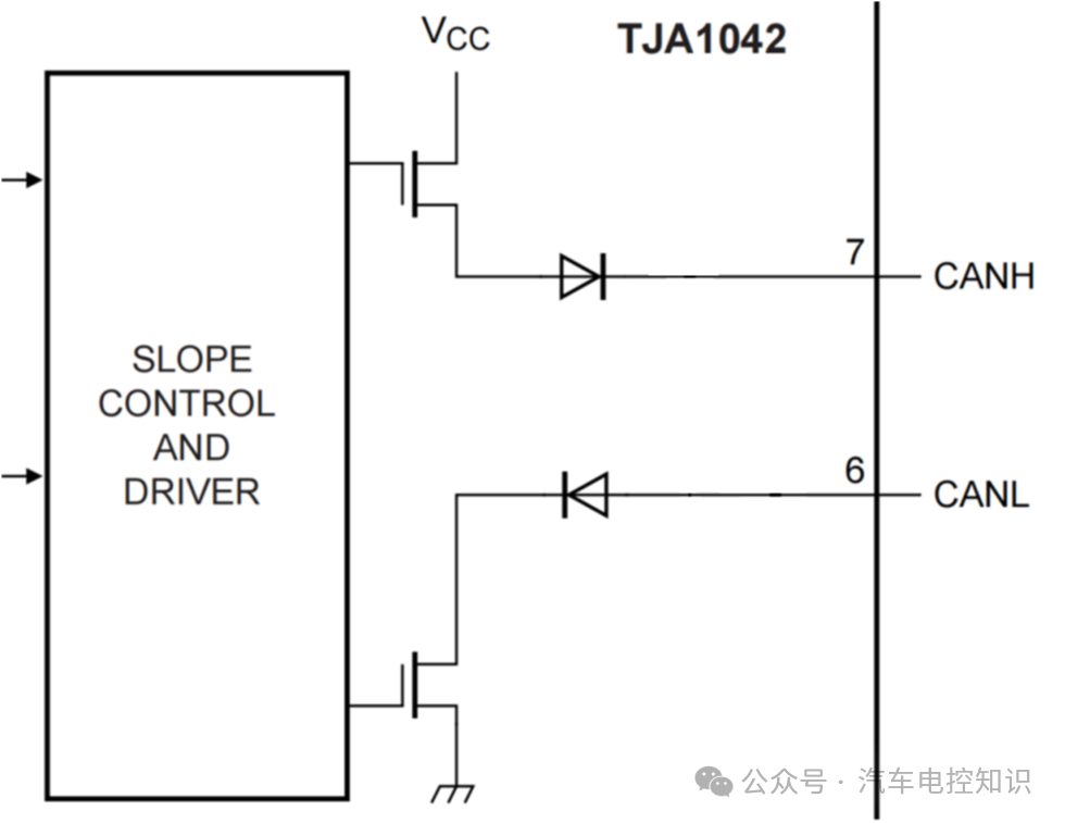
Transceiver internal circuit
This configuration allows the bus to easily achieve a dominant level (2V voltage difference) drive, while the recessive level (0V voltage difference) not only drives the voltage but also ensures a quick return to a stable voltage difference through the discharge of external termination resistors.
The differential transmission form of the CAN bus itself can eliminate most external common mode interference through the subtraction of CANH and CANL, such as common mode interference signals that have the same phase (direction) and amplitude (magnitude).
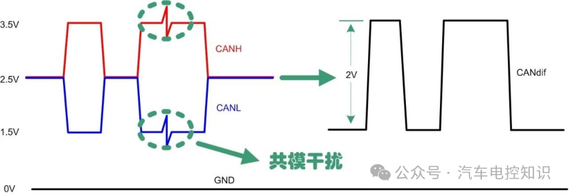
CAN transmission waveform – Anti-common mode interference
If the amplitude of the common mode interference signal is the same, both beingΔU, then the voltage difference of the CAN bus = (CANH+ΔU) – (CANL+ΔU) =CANH-CANL, which remains unchanged.
Additionally, some models (such asTJA1042T) of CAN transceivers have a special pin called SPLIT. SPLIT means to split or separate, and the SPLIT pin is internally connected to VCC and GND through two identical resistors and switches.The SPLIT pin is externally connected to CANH and CANL through two equal-sized resistors (e.g., 60 ohms).
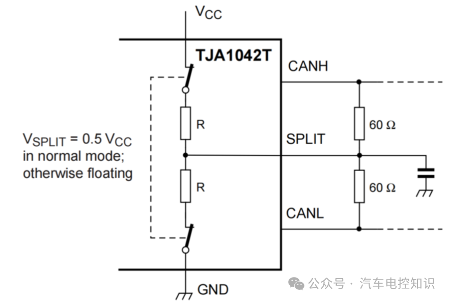
SPLIT pin internal circuit diagram
CAN transceivers have two operating modes: Normal and Standby. In Standby mode, both switches inside the SPLIT are open, and the output pins are in a floating state.
In Normal mode, the two switches inside the SPLIT close, outputting half the voltage of VCC through the SPLIT pin, which is 0.5VCC;
When VCC=5V, and the CAN bus is recessive (logic 1): the typical levels of CAN_H and CAN_L are both around 2.5V, resulting in a potential difference of CAN_H-CAN_L=0V.
Thus, the output of SPLIT at 0.5VCC=2.5V can provide a stronger recessive voltage level for the CAN bus, stabilizing the common mode output and minimizing the impact of common mode interference.
The SPLIT pin will also be connected to a decoupling capacitor, which can create a low-pass filter on the CANH and CANL lines, effectively reducing high-frequency noise emitted by the transceiver onto the bus.
This SPLIT terminal resistance circuit further enhances the CAN bus’s ability to resist common mode interference.
In other words, the CAN bus transceiver circuit already provides good resistance to common mode interference. If the PCB layout is reasonable and the external electromagnetic environment is not too harsh, then adding a common mode choke may not significantly improve the quality of the CAN waveform.
Moreover, adding a common mode inductor not only increases costs but may also have other drawbacks. For instance, although a single common mode inductor has a very small coil resistance and leakage inductance that affects differential signals, in a vehicle with multiple nodes and long distances, adding multiple common mode inductors may cause resonance, which could negatively impact the quality of the bus signal.
Of course, common mode inductors are necessary in certain situations, such as when EMC testing shows that the CAN bus radiation emissions exceed standards.
When adding a common mode inductor, another issue to consider is that inductive kickback can generate extremely high transient voltages. This transient voltage occurs at the input of the common mode inductor, which is between the common mode inductor and the transceiver. If not handled properly, this transient voltage can damage the transceiver, so a TVS Zener diode should be added between the two for transient protection, safeguarding the transceiver from high transient voltage damage.
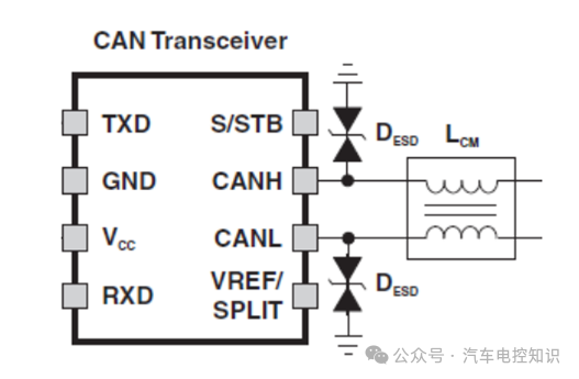
Adding TVS diodeDESD
The added TVS diode can not only prevent the transceiver from being impacted by the common mode inductor’s
transient voltage spikes but also protect against
electrostatic discharge (ESD) impacts.
5. Conclusion
The choke used in the CAN bus refers to a common mode inductor, which is used to suppress common mode interference signals. It can filter out common mode signal interference on the signal lines and also suppress electromagnetic interference emitted by the signal lines themselves.
Currently, CAN transceiver chips already possess good anti-static, anti-transient voltage and other EMC performance, so whether to use a choke should be determined based on the product’s own EMC test results and the overall vehicle’s electronic architecture.If a common mode choke must be used, it is recommended to add a TVS diode between the CANH, CANL pins, and the choke to suppress transient voltages and protect the transceiver.