 Source: 21ic Electronics NetworkOriginal Author:yyy71cjA stepper motor is a digital motor controlled by numbers, particularly suitable for precise control applications. Today, we will discuss the application of stepper motors in controlling a gimbal for accurate positioning, detailing the control of stepper motor movements.
01
Background and Introduction
First, the gimbal is controlled by a joystick controller, with speeds ranging from 0 to 63. Here, 0 means stop, and 63 is the fastest speed.The product model is shown in Figure 1:
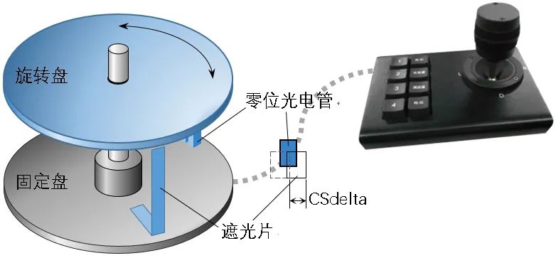 Figure 1: Gimbal Control ModelIn terms of control logic, the solution used here is a 2051 microcontroller as the stepper motor driver, and an 80C5x as the main control chip to implement product functions, forming a dual-machine system, as shown in Figure 2:
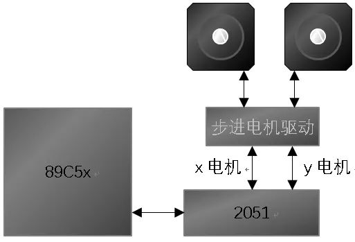 Figure 2: Gimbal Dual-Machine Control SystemThe dual-machine communication port line definitions are as follows:
sbit Cdata = P?^?; // ->2051sbit Cctrl = P?^?; // -INT0sbit Crclk = P?^?;sbit Ctclk = P?^?;02
Analysis and Countermeasures
We all know that the 51 microcontroller has some objective limitations.
First, it has a low operating frequency.The traditional 51 microcontroller operates at 12T, meaning that the execution speed of an instruction is 1/12 of the main frequency; thus, a 12M crystal oscillator executes instructions at only 1M. Of course, later variants of the 51 microcontroller operate at 1T, where most instructions execute at 1T, significantly improving execution speed.
The one used here is a 1T machine, as this product actually has two stepper motors. If the microcontroller is too slow, many product functions cannot be implemented smoothly. It is essential to fully utilize the JBC instruction to achieve conditional jumps, which corresponds to the C language statement _testbit_(abitvar). This small optimization is crucial for a complex, speed-sensitive product!
Secondly, there are few timers with short single timing durations.As the main control chip of a product, the 51 microcontroller is an 8-bit machine, and timer resources are very scarce. Therefore, this product utilizes Timer 0 in mode 3, splitting Timer 0 into two non-auto-reload 8-bit timers (at this time, the original Timer 1 can only serve as a baud rate generator
Since this mode cannot be modified once started, to greatly reduce the number of instructions, these two timers can operate in a pseudo-reload mode. That is, when the timer count register overflows to 0, this 0 is directly used as the reload data, avoiding the need for a command to perform the reload. For repeatedly running code, the benefit of saving even one instruction is significant.
The timer initialization code is as follows:
setBaud(BaudID); // First initialize Timer 1 as a baud rate generatorThird, memory resources are very limited.Variants of the 51 microcontroller exhibit a peculiar phenomenon where the code memory capacity is sufficiently large, while RAM (accessed using MOV) remains scarce. The execution time for external memory (accessed using MOVX) is also relatively high. Therefore, it becomes crucial to use resources wisely, and we often need to use code to save RAM.
03
Programming Wizard’s Perspective
The programming wizard’s perspective is to handle things in an object-oriented manner.When using stepper motors, control code should not be mixed in; only parameters (attributes) should be set, and actions (functions) should be called.
To reduce complex explanations, we will directly use the gimbal self-check as an example.The self-check process for the gimbal’s x-axis is shown in Figure 3:
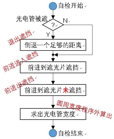 Figure 3: Self-Check ProcessPhotoelectric tube line definitions:
sbit Pos0x = Px^?; // x photoelectric tube signalLet’s take a look at the self-check code:
void SelfChk(void){       Pscx= (Pos0x)?0:1;      while(fx)      {       WDI = !WDI;      // ******** Feed Dog ********
       if(NdCtrlx)        {            NdCtrlx = 0;         if(fx)         {                   Pscx++;                   switch(Pscx)                   {                            case  2: xRun321(0,CVauto,CWavoid);                                        Sx = 0;                                        xRun();                                        break;                            case  1: Pscx = 3;                            case  3: Sx = 0;                                        xRun321(1,CVauto,0xFFFF);                                     xRun();                                        break;                            case  5: CSmaxx1 = Sx;                            case  4: Sx = 0;                                        break;                            case  6: CSdelta = Sx - 1;             // Self-check determines photoelectric tube width                                        fx = 0;                                        xStop();                 }         }        }      }}
From the self-check code, we can see that controlling the stepper motor only uses a few methods (functions/macros). This represents a high level of coding, where the code closely aligns with everyday semantics.
Next, let’s look at the method code for the stepper motor:
/*--------------------------------------------------------  Function: Prepare for x-direction movement           Fill in target Sendx, speed Vobj, running direction mmd  Parameters: o1:  running direction           o2:  target speed           o3:  target distance--------------------------------------------------------*/#define xRun321(o1,o2,o3)  {mmdx = o1;
                                       mmCmdx =((o2)>CVmax)?CVmax:o2;
                                       mmSx =o3; mmcx = 1;
                                     }
/*--------------------------------------------------------  Function: Start x-direction movement           Before calling, confirm target Sendx, speed Vobj, running direction mmd--------------------------------------------------------*/void xRun(void){      if(TR0) return;      TL0    = CT2Vooo; // Enter running time      NdCtrlx = 0;      TR0    = 1;}
/*--------------------------------------------------------  Function: Stop x-direction movement--------------------------------------------------------*/#define xStop(){mmCmdx = 0x40;mmcx = 1;}
Clearly, by setting the running parameters of the stepper motor and controlling its start and stop, we align with our everyday control habits, achieving a perfect unity of engineering and practical application.
04
Stepper Motor Motion Control Strategies
There are two ways to control stepper motor motion: one is speed control, and the other is endpoint control.
Speed Controlrefers to a real-time control method where only the target speed is specified, without controlling the target position. This control is arbitrary; it may involve changing from one speed to another or maintaining a certain speed; speed changes can be acceleration or deceleration; one speed can be 0 or not (as shown in Figure 4).
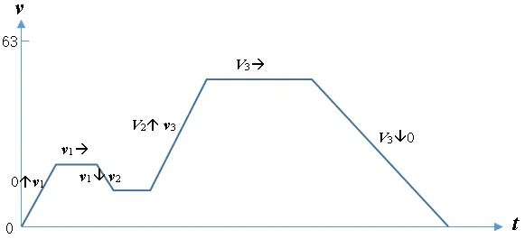 Figure 4: Speed Changes in Speed ControlTarget Controlrefers to the control method of reproducing pre-stored point coordinates, reading the current target endpoint coordinates, and moving to that point at a certain speed. This control has a defined target and speed, requiring precise positioning (as shown in Figure 5).
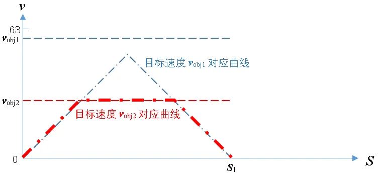 Figure 5: Speed and Distance Curve for Endpoint ControlOnce the stepper motor control strategy is determined, we need to continuously scan the control strategy. If any changes occur, we respond immediately. These time-based differential controls are implemented using programs that utilize timers, ensuring the uniformity of time differentials, thus providing a stable experience.In fact, this demand is a definite, mechanical requirement that we can integrate into the stepper motor’s timing. This way, we can obtain a differential control logic diagram for the stepper motor (as shown in Figure 6).
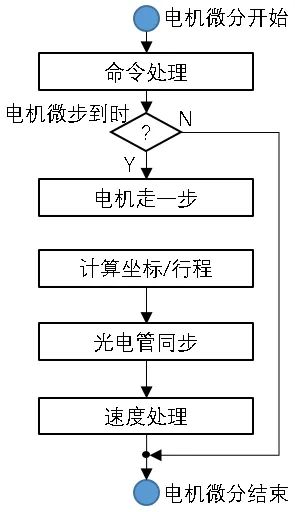 Figure 6: Stepper Motor Control Differential Flowchart
05
Code
I know many friends dislike verbose explanations and prefer code,so I won’t elaborate further; you can just copy the code.
The ISR for Timer 0 (x motor) is as follows:
void Timer0(void) interrupt 1 using 1{ static UINT data Dis=0; // Remaining distance static bit D=0; // Movement direction static UCH data Vend=0; // Target speed static UCH data V=0; // Current speed static UCH data lps=0; // Timer delay multiplier counter static bit Wavoid=0; //-------------------------------------------------------------------------------- if(_testbit_(mmcx)) // Immediate execution command exists { switch(mmCmdx) { case 0x40: // Stop if(Dis>V)Dis = V; Vend= 0; mmCmdx = 0x00; break; default : // Start command interpretation: mmcx = 0 indicates speed change, other commands must mmcx = 1 if(V&&(D!=mmdx)) // If speed is greater than 0 and direction is reversed, execute deceleration to automatic stop { if(Vend){Dis= V; Vend = 0;} } else { D = mmdx; Vend = mmCmdx; Sendx =mmSx; if(Sendx<(CSmaxx1)) Dis= (fx)?(Sendx -Sx):((D)?((Sendx>=Sx)?(Sendx-Sx):(CSmaxx1-Sx+Sendx)):((Sendx<=Sx)?(Sx-Sendx):(CSmaxx1-Sendx+Sx))); else Dis= 0xFFFF; } if(!Dis)StopRunx(); if(!lps) lps = CT2Vooo; // Enter first step at maximum speed } } // Running processing if(++lps) return; // Extend timer timing time, lps increments to overflow (==0) before performing a movement processing SendMx(); // Move one step according to current direction NextPx(); // Calculate the next circular coordinate Sx and remaining distance Dis (distance cannot exceed maximum circular coordinate, automatically calculate the nearest distance and direction to reach the target) WidAvd(); // Synchronize processing at the photoelectric tube (self-check positive direction from unblocked to blocked is 0, from blocked to unblocked is the photoelectric tube width, reverse processing) NxtxAn(); // Calculate the next speed parameters}The code for moving the stepper motor one step is as follows (this code is hardware-dependent and is for reference only):
#define SendMx(){
                            Cctrl = 1; Cdata =0; Cctrl = 0;
                            Cctrl = 1; Cdata =!D; Cctrl = 0;
                       }
The code for processing coordinates and distance after the stepper motor moves one step is as follows:
#define NextPx(){
                            if(fx)
                            {
                                  Sx++;
                            }
                            else
                            {
                                  if(D)
                                  {
                                       Sx++;
                                       if(Sx>=CSmaxx1)Sx = 0;
                                  }
                                  else
                                  {
                                       if(Sx)Sx--; else Sx = CSmaxx1 - 1;
                                  }
                            }
                            if(Dis &&(Dis<(CSmaxx1))) Dis--;
                        }
The code for synchronizing processing after detecting the photoelectric tube is as follows:
#define WidAvd(){
                            if(Wavoid)
                            {
                                  if(Pos0x)
                                  {
                                       Wavoid =0;
                                       if(fx)if(Pscx==5) NdCtrlx = 1;
                                  }
                            }
                            else
                            {
                                  if(!Pos0x)
                                  {
                                       Wavoid =1;
                                       if(fx)
                                       {
                                             if((Pscx==3)||(Pscx==4))NdCtrlx = 1;
                                       }
                                       else
                                       {
                                             Sx= (D)?0:CSdelta;
                                       }
                                  }
                            }
                       }
The code for processing speed after the stepper motor moves one step is as follows:
#define NxtxAn(){
                            if(Dis)
                            {
                                  if(Dis>V)
                                  {
                                       if(V<Vend)
                                       {
                                             V++;
                                       }
                                       else
                                       {
                                             if(V>Vend)V--;
                                       }
                                  }
                                  else
                                  {
                                       V--;
                                  }
                                  lps = CxT2Vmin+ V;
                            }
                            else
                            {
                                  StopRunx();
                            }
                       }
06
Related Issues and Solutions
1.Since stepper motors are devices with low power conversion efficiency, when there is a conflict between load and output power, it is crucial to ensure that the device does not lose steps. Minimizing the impact of the load is of utmost importance, such as reducing load mass and lowering motion resistance.
2.Choosing stepper motors with low copper and iron losses is an optimal solution to improve the load capacity of stepper motors while maintaining a certain size, provided you can accept the cost increase.
3.Sudden speed changes can easily lead to stepper motor loss of steps, primarily due to the desire for both small size and high speed in stepper motors, which causes the motor power to be insufficient for speed changes. Using appropriate acceleration curves can help mitigate step loss without increasing motor power.
4.Synchronizing the position of the photoelectric tube is an effective way to avoid cumulative errors caused by mechanical discrepancies during stepper motor control. Since such errors typically accumulate only during full rotations, synchronizing each time the zero-position photoelectric tube is passed can eliminate them.
5.For handling position-speed deviations during calculations, when approaching the specified target, if the speed should become 0 according to the acceleration-deceleration curve, maintain speed at 1 until reaching the endpoint. When reaching the specified target, if the speed cannot reach 0 according to the acceleration-deceleration curve, directly reduce the speed to 0 upon reaching the endpoint.
Although this approach may seem unreasonable, the impact of forced correction when the calculation error is ±1 can be negligible.
6.If the stepper motor experiences significant shaking at a certain speed (with noticeably increased operating noise), modifying the load structure and mass can change the product’s inherent resonant frequency, avoiding shaking caused by structural resonance points.
。
END
The reproduced content only represents the author’s views
It does not represent the position of the Institute of Semiconductors, Chinese Academy of Sciences
Editor: Renowned Unknown Wei Classmate
Editor: Six Dollar Fish
Submission Email: [email protected]
Previous Recommendations1. The Semiconductor Institute has made progress in the research of bionic covering neuron models and learning methods.2. The Semiconductor Institute has made significant progress in inverted structure perovskite solar cells.3. Why is copper used as interconnect metal in chips?4. What exactly is 7nm in chips?5. Silicon-based integrated optical quantum chip technology.6. How anomalous is the quantum anomalous Hall effect? It may lead to the next revolution in information technology!