Before the advent of PCBs, circuits were made through point-to-point wiring. This method had low reliability, as aging circuits could lead to wire breakage, resulting in open or short circuits at connection points. Wire winding technology was a significant advancement in circuit technology, enhancing the durability and replaceability of wires by winding small diameter wires around connection point pillars.
As the electronics industry transitioned from vacuum tubes and relays to silicon semiconductors and integrated circuits, the size and cost of electronic components also decreased. Electronic products increasingly appeared in the consumer sector, prompting manufacturers to seek smaller and more cost-effective solutions. Thus, PCBs were born.
All electronic products require PCBs, and the market trends for PCBs are almost a barometer for the electronics industry. However, with the development of high-end, miniaturized electronic products such as mobile phones, laptops, and PDAs, the demand for flexible PCBs (FPCs) has surged. PCB manufacturers are accelerating the development of thinner, lighter, and denser FPCs.
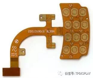
1. Single-layer FPC
It has a layer of conductive patterns etched by chemicals, with the conductive pattern layer on the flexible insulating substrate made of rolled copper foil. The insulating substrate can be polyimide, polyethylene terephthalate, aramid fiber ester, or polyvinyl chloride. Single-layer FPCs can be further divided into the following four subcategories:
1. No Cover Layer Single-sided Connection
The wire patterns are on the insulating substrate, with no cover layer on the wire surface. Interconnections are achieved using soldering, melting, or pressure welding, commonly used in early telephones.
2. Cover Layer Single-sided Connection
Compared to the previous category, it has an additional cover layer on the wire surface. The pads need to be exposed during covering, which can be simply left uncovered in the end regions. This is the most widely used type of single-sided flexible PCB, found in automotive instruments and electronic devices.
3. No Cover Layer Double-sided Connection
The connection pads can connect on both the front and back of the wires. A through hole is opened on the insulating substrate at the pad location, which can be formed by punching, etching, or other mechanical methods.
4. Cover Layer Double-sided Connection
Unlike the previous category, it has a cover layer on the surface, with through holes allowing connections on both sides while maintaining the cover layer, made of two layers of insulating material and one layer of metal conductor.
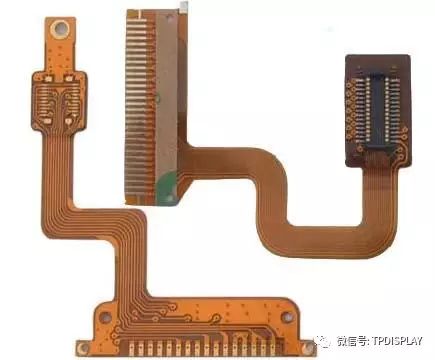
Double-sided FPC has a layer of etched conductive patterns on both sides of the insulating base film, increasing the wiring density per unit area. Metallized holes connect the patterns on both sides of the insulating material to form conductive paths, meeting design and functional requirements for flexibility. The cover film can protect single and double-sided wires and indicate the placement of components. Depending on requirements, metallized holes and cover layers can be optional; this type of FPC is less commonly used.
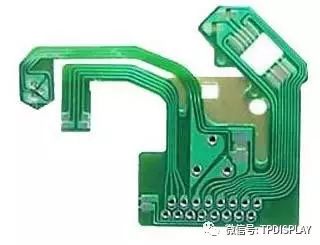
Multi-layer FPC consists of three or more layers of single-sided or double-sided flexible circuits laminated together, with drilled and plated metallized holes forming conductive paths between different layers. This eliminates the need for complex soldering processes. Multi-layer circuits offer significant functional differences in higher reliability, better thermal conductivity, and easier assembly performance.
The advantages include the thin film substrate being lightweight and having excellent electrical properties, such as a low dielectric constant. Multi-layer flexible PCBs made from polyimide films are about one-third lighter than rigid epoxy glass multi-layer PCBs, but they lose the excellent flexibility of single-sided and double-sided flexible PCBs, most of which do not require flexibility. Multi-layer FPCs can be further divided into the following types:
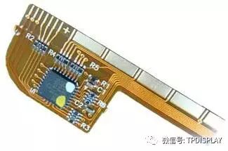
1. Flexible Insulating Substrate Finished Product
This type is manufactured on a flexible insulating substrate, with the finished product specified to be bendable. This structure usually involves bonding the two sides of many single-sided or double-sided microstrip flexible PCBs together, but the center part is not bonded, allowing for high flexibility. To achieve high flexibility, a thin suitable coating, such as polyimide, can replace a thicker laminated cover layer on the wire layer.
2. Soft Insulating Substrate Finished Product
This type is manufactured on a soft insulating substrate, with the finished product not specified to be bendable. These multi-layer FPCs are laminated from soft insulating materials, such as polyimide films, and lose inherent flexibility after lamination.
Disclaimer: The copyright of this article belongs to the original author and does not represent the association’s views. Articles promoted by the “Jiangxi Province Electronic Circuit Industry Association” are for sharing purposes only and do not represent this account’s stance. If there are copyright issues, please contact us for deletion.