1. What is an Interrupt? It interrupts the normal execution of the CPU’s program to handle an urgent program, and after processing, it returns to the original paused program to continue execution. As shown in the figure below, for example, I am doing homework, and suddenly feel thirsty, so I go to drink water. The white area represents the time wasted drinking water. After drinking, I continue doing homework, and the homework time needs to be extended by the time spent drinking water.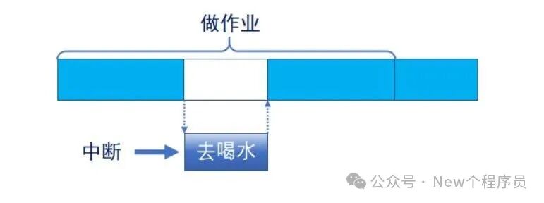 The significance of interrupts: efficiently handle urgent programs without continuously occupying CPU resources.2. NVIC NVIC stands for Nested Vectored Interrupt Controller, which is part of the core, supporting 256 interrupts (16 core + 240 external), supporting 256 priorities, and allowing trimming. NVIC can be understood as the master switch for all interrupts.The following is the internal resource of STM32F103xx.
| STM32 Model | Core Interrupts | External Interrupts | Interrupt Priorities |
| STM32F103xx | 10 | 60 | 16 |
1. Introduction to Common NVIC Registers, as shown in the figure below.
|
NVIC Related Registers |
Bit Count | Number of Registers | Remarks |
|
Interrupt Set Enable Register (ISER) |
32 | 8 |
Each bit controls one interrupt |
|
Interrupt Clear Enable Register (ICER) |
32 | 8 |
Each bit controls one interrupt |
|
Application Interrupt and Reset Control Register (AIRCR) |
32 | 1 |
Bits [10:8] control priority grouping |
|
Interrupt Priority Register (IPR) |
8 | 240 |
8 bits correspond to one interrupt, while STM32 only uses the high 4 bits |
NVIC also has less common functions such as interrupt pending, un-pending, and activation flags.
2. Interrupt Priority Grouping
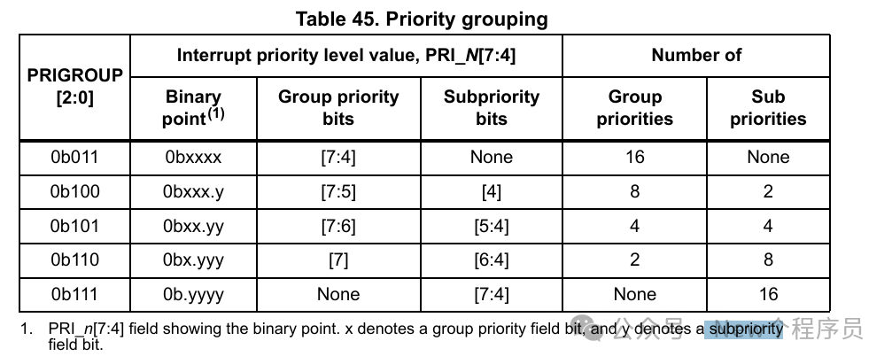
There are a total of 5 groups, which are easy to remember, priority group numbers correspond exactly to the bit numbers of preemption priority.
| Priority Group | AIRCR[10:8] | IPRxbit[7:4] Allocation | Allocation Result |
| 0 | 111 | None:[7:4] | 0 bits preemption priority, 4 bits response priority |
| 1 | 110 | [7]:[6:4] | 1 bit preemption priority, 3 bits response priority |
| 2 | 101 | [7:6]:[5:4] | 2 bits preemption priority, 2 bits response priority |
| 3 | 100 | [7:5]:[4] | 3 bits preemption priority, 1 bit response priority |
| 4 | 011 | [7:4]:None | 4 bits preemption priority, 0 bits response priority |
The reference is STM32F10xx – Cortex-M3 Programming Manual, PRIGROUP[2:0] is AIRCR[10:8], Group priority is preemption priority, Subpriority is response priority.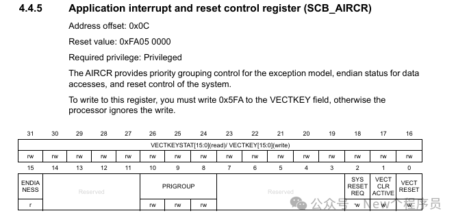
3. Interrupt Priority
Preemption Priority: A high preemption priority can interrupt a currently executing low preemption priority interrupt. This means that when a low preemption priority program is executing, a high preemption priority can directly interrupt it, stopping its execution to execute the high preemption priority program.
Response Priority: When the preemption priorities are the same, the one with the higher response priority executes first, but they cannot interrupt each other. The one with the higher response priority can only execute after the other has finished.
Natural Priority: The priority of the interrupt vector table, which is a system default priority. The interrupt vector table defines a block of fixed memory, aligned to 4 bytes, storing the starting addresses of various interrupt service functions. This can be viewed in the startup file .s or refer to the STM32F10xx Technical Reference Manual section 9.1.2.
Note: The smaller the value, the higher the priority, which is somewhat similar to ranking in grades. When both preemption and response are the same, the one with the higher natural priority executes first.
In summary: Preemption Priority > Response Priority > Natural Priority.
4. Using NVIC
1. Set Interrupt Group: HAL_NVIC_SetPriorityGrouping.
2. Set Interrupt Priority: HAL_NVIC_SetPriority.
3. Enable Interrupt: HAL_NVIC_EnableIRQ.
5. Basic Concept of EXTI
EXTI stands for External (Extended) Interrupt/Event Controller, which includes 20 edge detectors that generate event/interrupt requests, totaling: 20 EXTI lines (F1).
Understanding Interrupts and Events:
Interrupt: Must enter NVIC, has a corresponding interrupt service function, requires CPU processing.
Event: Does not enter NVIC, only used for internal hardware automatic control, such as: TIM, DMA, ADC
6. Working Principle of EXTI Interrupt
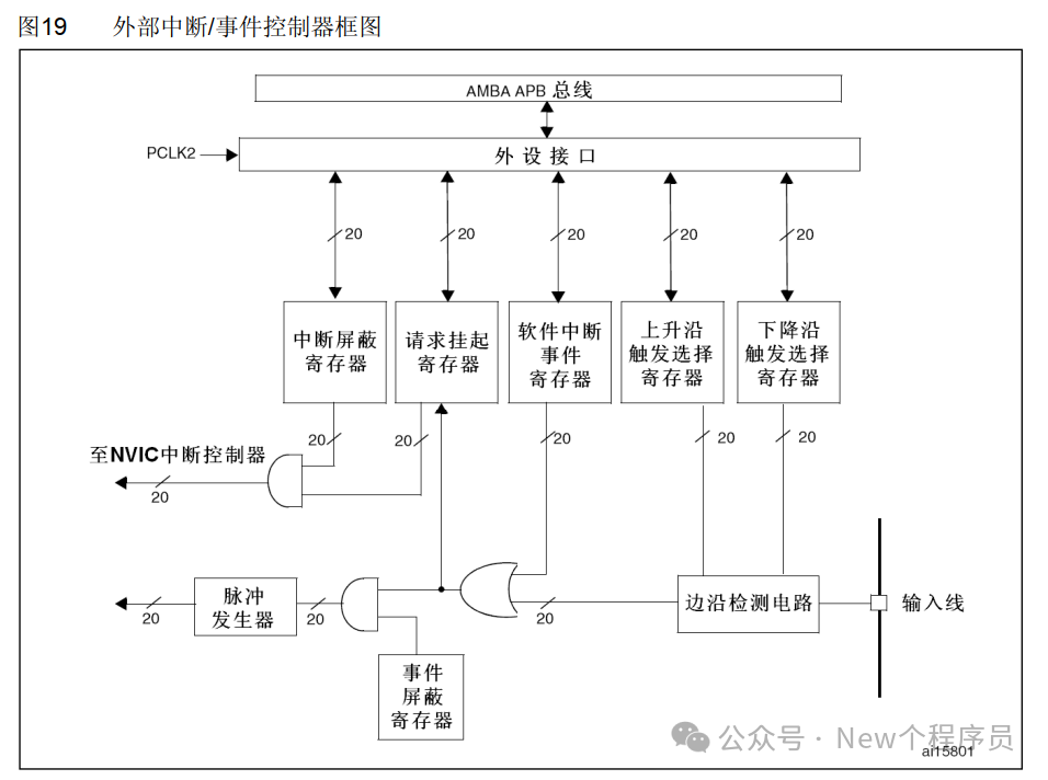
As shown in the figure below, input signals from the input line are detected by the edge detection circuit, which can be set to trigger on rising/falling edges through the rising/falling edge trigger selection register.
Software interrupt event register, this can be configured through software or hardware, generally selecting hardware configuration, which is the line from the edge detection circuit. If triggered on the rising edge, it will set to 1, then make the request pending register set to 1, and configure the interrupt mask register to 1, passing through an AND gate to trigger the NVIC interrupt controller.
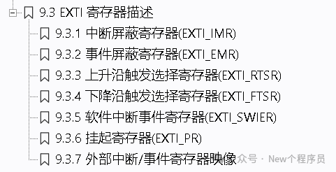
To understand the EXTI registers, refer to the STM32F10xx Technical Reference Manual section 9.3, which will provide specific explanations and configurations.
7. AFIO
AFIO stands for Alternate Function IO, which is mainly used for remapping and external interrupt mapping configuration.
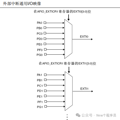
For external interrupts, the AFIO_EXTICR1~4 registers can be used to configure which IO pin corresponds to interrupt lines 0~15, and the mapping relationship between IO pins and EXTI interrupt lines is as follows.
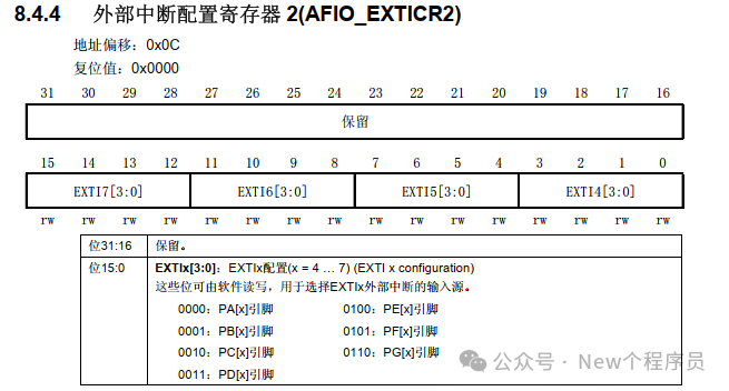
Taking the AFIO_EXTICR2 register as an example, only the low 16 bits are used, with 4 bits representing one interrupt line. Different values can be configured to select different IO pins.
8. Steps to Configure EXTI External Interrupt
1. Enable GPIO clock.
2. Set GPIO input mode: pull-up/pull-down/floating input.
3. Enable AFIO clock: set AFIO clock enable register.
4. Set the relationship between EXTI interrupt lines and IO.
5. Set EXTI registers: interrupt mask, rising/falling edge.
6. Set NVIC: set priority grouping, set priority, enable interrupt.
7. Design interrupt service function.
9. Using EXTI External Interrupt HAL Functions
1. Enable GPIO clock: __HAL_RCC_GPIOx_CLK_ENABLE.
2. GPIO/AFIO/EXTI: Call HAL_GPIO_Init in Mx_GPIO_Init.
3. Set interrupt grouping: HAL_NVIC_SetPriorityGrouping, this function only needs to be set once! Call it in HAL_Init().
4. Set interrupt priority: HAL_NVIC_SetPriority.
5. Enable interrupt: HAL_NVIC_EnableIRQ.
6. Design interrupt service function: EXTIx_IRQHandle, this function is located in it.c, generally written automatically after generating the program with Cube Mx, in this function, the common processing function HAL_GPIO_EXTI_IRQHandler will be called, and in the common processing function, the callback function HAL_GPIO_EXTI_Callback will be called, where you can directly write logic code. Note that all EXTI interrupts call the same callback function, so you need to perform checks in the callback function.
10. Conclusion
Finally, due to the extensive content and the complexity of HAL functions, which are more difficult than the standard library, with too many layers of encapsulation, the above content is not comprehensive, and further research and study are needed. The above functions only list the function names.