
Whether for beginners or electronic enthusiasts who have dabbled in microcontrollers, car projects are a common experience. Today, I will introduce a project based on the STM32 ultrasonic obstacle avoidance car. This was also one of my course projects, and I am sharing it as open source. The full text is over 5000 words, packed with useful information, so keep reading! I guarantee you will gain a lot.

Processor Circuit Design
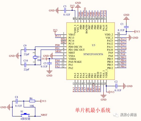
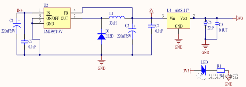
Power Supply Module Design
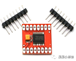
Motor Driver Module Design
Motor Driver Pin Table
 1 Control Chip: TB6612
 2 Number of Control Chips: 2
 3    TB6612 Pin Allocation for Chip 1:
 4     VM         PWMA--------->TIM1_CH1(PA8)
 5     VCC        AIN2--------->GPIOB_12
 6     GND        AIN1--------->GPIOB_13
 7     AO1        STBY--------->GPIOB_14
 8     AO2        BIN1--------->GPIOB_15
 9     BO2        BIN2--------->GPIOA_12
10     BO1        PWMB--------->TIM1_CH2(PA9)
11     GND        GND
12    TB6612 Pin Allocation for Chip 2:
13     VM         PWMA--------->TIM1_CH3(PA10)
14     VCC        AIN2--------->GPIOB_5
15     GND        AIN1--------->GPIOB_6
16     AO1        STBY--------->GPIOB_7
17     AO2        BIN1--------->GPIOB_8
18     BO2        BIN2--------->GPIOA_9
19     BO1        PWMB--------->TIM1_CH4(PA11)
20     GND        GND
21 Truth Table
22     AIN1   0     1     0     1
23     AIN2   0     0     1     1
24     BIN1   0     1     0     1
25     BIN2   0     0     1     1
26           Stop  Forward  Reverse  Brake
Timer Configuration for Motor
 1 // Initialize TIMX, set TIMx's ARR, PSC
 2 // arr: auto-reload initial value, psc is the prescale value, both control the timer clock cycle
 3 // Select Timer TIM1
 4 static void TB6612_ADVANCE_TIM1_Mode_Config(TIM_TypeDef* TIMx,uint16_t arr,uint16_t psc,uint16_t duty)
 5 {
 6    //----------------- Timer Base Structure Initialization -------------------------/
 7    TIM_TimeBaseInitTypeDef TIM_TimeStructure;
 8    /* Enable Timer 1 clock, i.e., internal clock CK_INT=72M */
 9    RCC_APB2PeriphClockCmd(RCC_APB2Periph_TIM1,ENABLE);
10    TIM_DeInit(TIMx);
11    /* Internal clock as counter clock, 72MHZ */
12    TIM_InternalClockConfig(TIMx);
13    /* Auto-reload register value, after TIM_Period+1 frequencies generate an update or interrupt */
14    TIM_TimeStructure.TIM_Period=arr;
15    /* Clock prescale coefficient is 71, driving counter clock CK_CNT=CK_INT/(71+1)=1MHZ */
16    TIM_TimeStructure.TIM_Prescaler=psc-1;
17    /* Set clock division, TIM_CKD_DIV1=0, PWM wave has no delay */
18    TIM_TimeStructure.TIM_ClockDivision=TIM_CKD_DIV1;
19    /* Up counting mode */
20    TIM_TimeStructure.TIM_CounterMode=TIM_CounterMode_Up;
21    /* Repeat counter */
22    TIM_TimeStructure.TIM_RepetitionCounter=0;
23    /* Initialize timer */
24    TIM_TimeBaseInit(TIMx,&TIM_TimeStructure);
25    /* Enable ARR preload register (shadow register) */
26    TIM_ARRPreloadConfig(TIMx,ENABLE);
27    //----------------- Output Compare Structure Initialization -----------------------/
28    TIM_OCInitTypeDef   TIM_OCInitStructure;
29    /* PWM mode setting, set to PWM mode 1 */
30    TIM_OCInitStructure.TIM_OCMode=TIM_OCMode_PWM1;
31    /* PWM output enables the corresponding IO port to output signals */
32    TIM_OCInitStructure.TIM_OutputState=TIM_OutputState_Enable;
33    /* Set duty cycle size, CCR1[15:0]: value of capture/compare channel 1, if CC1 channel is configured for output: CCR1 contains the value loaded into the current capture/compare 1 register (preload value). */
34    TIM_OCInitStructure.TIM_Pulse=duty;
35    /* Output channel level polarity setting */
36    TIM_OCInitStructure.TIM_OCPolarity=TIM_OCPolarity_High;
37    /* Initialize output compare parameters */
38    TIM_OC1Init(TIMx,&TIM_OCInitStructure);// Initialize TIM1 Channel 1
39    TIM_OC2Init(TIMx,&TIM_OCInitStructure);// Initialize TIM1 Channel 2
40    TIM_OC3Init(TIMx,&TIM_OCInitStructure);// Initialize TIM1 Channel 3
41    TIM_OC4Init(TIMx,&TIM_OCInitStructure);// Initialize TIM1 Channel 4
42    /* Auto-reload */
43    TIM_OC1PreloadConfig(TIMx,TIM_OCPreload_Enable);
44    TIM_OC2PreloadConfig(TIMx,TIM_OCPreload_Enable);
45    TIM_OC3PreloadConfig(TIMx,TIM_OCPreload_Enable);
46    TIM_OC4PreloadConfig(TIMx,TIM_OCPreload_Enable);
47    /* Enable counter */
48    TIM_Cmd(TIMx,ENABLE);
49    /* Main output enable, if the corresponding enable bit is set (CCxE, CCxNE bits of TIMx_CCER register), OC and OCN outputs are enabled. */
50    TIM_CtrlPWMOutputs(TIMx,ENABLE);
51 }
52 // Advanced timer output channel initialization function
53 static void TB6612_ADVANCE_TIM_Gpio_Config()
54 {
55    GPIO_InitTypeDef  GPIO_InitStruct;
56    /*---------- Channel 1 Configuration --------------*/
57    /* Timer 1 output compare channel */
58    RCC_APB2PeriphClockCmd(RCC_APB2Periph_GPIOA,ENABLE);
59    /* Configure as alternate push-pull output */
60    GPIO_InitStruct.GPIO_Mode=GPIO_Mode_AF_PP;
61    GPIO_InitStruct.GPIO_Pin=GPIO_Pin_8;
62    GPIO_InitStruct.GPIO_Speed=GPIO_Speed_50MHz;
63    GPIO_Init(GPIOA,&GPIO_InitStruct);
64    /*----------- Channel 2 Configuration -------------*/
65    /* Timer 1 output compare channel */
66    /* Configure as alternate push-pull output */
67    GPIO_InitStruct.GPIO_Mode=GPIO_Mode_AF_PP;
68    GPIO_InitStruct.GPIO_Pin=GPIO_Pin_11;
69    GPIO_InitStruct.GPIO_Speed=GPIO_Speed_50MHz;
70    GPIO_Init(GPIOA,&GPIO_InitStruct);
71     /*----------- Channel 3 Configuration -------------*/
72    /* Timer 1 output compare channel */
73    /* Configure as alternate push-pull output */
74    GPIO_InitStruct.GPIO_Mode=GPIO_Mode_AF_PP;
75    GPIO_InitStruct.GPIO_Pin=GPIO_Pin_9;
76    GPIO_InitStruct.GPIO_Speed=GPIO_Speed_50MHz;
77    GPIO_Init(GPIOA,&GPIO_InitStruct);
78     /*----------- Channel 4 Configuration -------------*/
79    /* Timer 1 output compare channel */
80    /* Configure as alternate push-pull output */
81    GPIO_InitStruct.GPIO_Mode=GPIO_Mode_AF_PP;
82    GPIO_InitStruct.GPIO_Pin=GPIO_Pin_10;
83    GPIO_InitStruct.GPIO_Speed=GPIO_Speed_50MHz;
84    GPIO_Init(GPIOA,&GPIO_InitStruct);
85 }
Ultrasonic Module
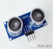
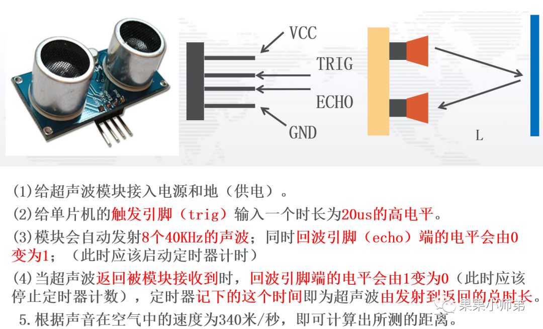
Important Ultrasonic Code (for reference)
 1/* Get the duration of the received high level (us) */
 2 uint32_t Get_HC_SR04_Time(void)
 3 {
 4    uint32_t t=0;
 5    t=Acoustic_Distance_Count*1000;//us
 6    t+=TIM_GetCounter(TIM2);// Get us
 7    TIM2->CNT =0;
 8    Acoustic_Distance_Count=0;
 9    Systic_Delay_us(100);
10    return t;
11 }
12/* Get distance */
13 void Get_HC_SR04_Distance(void)
14 {
15    static uint16_t count=0;
16    switch(count)
17    {
18        case 1:
19        {
20            GPIO_SetBits(Acoustic_Port,HC_SR04_Trig);// Trig sends a high level greater than 10us
21        }break;
22
23        case 15:
24        {
25            count=0;
26            GPIO_ResetBits(Acoustic_Port,HC_SR04_Trig);
27            while(GPIO_ReadInputDataBit(Acoustic_Port,HC_SR04_Echo)==0);// When Echo is 0, start the timer
28            Open_Tim2();
29            while(GPIO_ReadInputDataBit(Acoustic_Port,HC_SR04_Echo)==1);// When Echo is 1, stop the timer
30            Close_Tim2();
31            HC_SR04_Distance=(float)(Get_HC_SR04_Time()/5.78);
32
33        }break;
34        default:break;
35    }
36    count++;
37 }
Servo Module
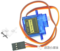
Important Servo Code (for reference)
 1/** PWM Pin Initialization */
 2 static void SERVO_Gpio_Init(void)
 3 {
 4    GPIO_InitTypeDef  GPIO_InitStruct;
 5    /*---------- Channel 2 Configuration --------------*/
 6    /* Timer 3 output compare channel */
 7    RCC_APB2PeriphClockCmd(RCC_APB2Periph_GPIOA,ENABLE);
 8    /* Configure as alternate push-pull output */
 9    GPIO_InitStruct.GPIO_Mode=GPIO_Mode_AF_PP;
10    GPIO_InitStruct.GPIO_Pin=GPIO_Pin_7;
11    GPIO_InitStruct.GPIO_Speed=GPIO_Speed_50MHz;
12    GPIO_Init(GPIOA,&GPIO_InitStruct);
13 }
14// Timer 3 initialization, set TIMx's ARR, PSC
15// arr: auto-reload initial value, psc is the prescale value, both control the timer clock cycle
16 static void SERVO_TIM_Config(TIM_TypeDef* TIMx,uint16_t arr,uint16_t psc,uint16_t duty)
17 {
18    //----------------- Timer Base Structure Initialization -------------------------/
19    TIM_TimeBaseInitTypeDef TIM_TimeStructure;
20    /* Enable Timer 3 clock, i.e., internal clock CK_INT=72M */
21    RCC_APB1PeriphClockCmd(RCC_APB1Periph_TIM3,ENABLE);
22    TIM_DeInit(TIMx);
23    /* Internal clock as counter clock, 72MHZ */
24    TIM_InternalClockConfig(TIMx);
25    /* Auto-reload register value, after TIM_Period+1 frequencies generate an update or interrupt */
26    TIM_TimeStructure.TIM_Period=arr;//1000 When the timer counts from 0 to 999, it produces one timing cycle
27    /* Clock prescale coefficient is 71, driving counter clock CK_CNT=CK_INT/(1440-1+1)=0.05MHZ */
28    TIM_TimeStructure.TIM_Prescaler=psc-1;;//1400  // Timer frequency is 5KHZ
29    /* Set clock division, TIM_CKD_DIV1=0, PWM wave has no delay */
30    TIM_TimeStructure.TIM_ClockDivision=TIM_CKD_DIV1;
31    /* Up counting mode */
32    TIM_TimeStructure.TIM_CounterMode=TIM_CounterMode_Up;
33    /* Repeat counter */
34    TIM_TimeStructure.TIM_RepetitionCounter=0;
35    /* Initialize timer */
36    TIM_TimeBaseInit(TIMx,&TIM_TimeStructure);
37    /* Enable ARR preload register (shadow register) */
38    TIM_ARRPreloadConfig(TIMx,ENABLE);
39    //----------------- Output Compare Structure Initialization Start -----------------------/
40    TIM_OCInitTypeDef   TIM_OCInitStructure;
41    /* PWM mode setting, set to PWM mode 1 */
42    TIM_OCInitStructure.TIM_OCMode=TIM_OCMode_PWM1;
43    /* PWM output enables the corresponding IO port to output signals */
44    TIM_OCInitStructure.TIM_OutputState=TIM_OutputState_Enable;
45    /* Set duty cycle size, CCR1[15:0]: value of capture/compare channel 1, if CC1 channel is configured for output: CCR1 contains the value loaded into the current capture/compare 1 register (preload value). */
46    TIM_OCInitStructure.TIM_Pulse=duty;   // Duty cycle size
47    /* Output channel level polarity setting */
48    TIM_OCInitStructure.TIM_OCPolarity=TIM_OCPolarity_High;
49    /* Initialize output compare parameters */
50    TIM_OC2Init(TIMx,&TIM_OCInitStructure);
51    //----------------- Output Compare Structure Initialization End -----------------------/
52    /* Auto-reload */
53    TIM_OC2PreloadConfig(TIMx,TIM_OCPreload_Enable);
54    /* Enable counter */
55    TIM_Cmd(TIMx,ENABLE);
56    /* Main output enable, if the corresponding enable bit is set (CCxE, CCxNE bits of TIMx_CCER register), OC and OCN outputs are enabled. */
57    TIM_CtrlPWMOutputs(TIMx,ENABLE);
58 }
59 /* Servo PWM initialization
60   Each increase of 0.1ms corresponds to a 9-degree turn of the servo
610.5ms---------0
621.0ms---------45
631.5ms---------90
642.0ms---------135
652.5ms-----------180
662.1ms    turn_left=150
670.8ms    turn_right=25
681.3ms    turn_front=75
6920ms base pulse, if you want the servo to turn 90 degrees, a high level lasting for 1.5ms should be generated, with a period of 20ms, giving duty=1.5/20=7.5% , and the timer's auto-reload register arr is set to 1000, so duty=75, the duty cycle is 75/1000=7.5%.
70 */
71 void SERVO_Init(void)
72 {
73    SERVO_Gpio_Init();
74    SERVO_TIM_Config(TIM3,1000,1440,turn_front);
75 /** We set the value of the auto-reload register arr to 1000, and set the clock prescaler to 1440, then
76 the clock for the counter: CK_CNT = CK_INT / (1440-1+1)=0.05M, so the time for the counter to count once is:
77 1/CK_CNT=20us, when the counter counts to the value of ARR 1000, it generates an interrupt, then the time for one interrupt
78 is: 1/CK_CNT*ARR=20ms.
79 The frequency of the PWM signal f = TIM_CLK/{(ARR+1)*(PSC+1)}  TIM_CLK=72MHZ
80               = 72 000 000/(1000*1440)=5KHZ
81 */
82 }
83 /* Servo Angle Control */
84 void SERVO_Angle_Control(uint16_t Compare2)
85 {
86    TIM_SetCompare2(TIM3,Compare2);
87 }
Encoder Module
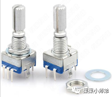
OLED Display Module
This Week’s Benefits


1
“Open Source Project! Use ZigBee Module for Smart Home Remote Voice Control”
2
“Reviewing 14 Mainstream Embedded Operating Systems, How Many Do You Recognize?”
3
“Review | Common Classic Interview Questions for Embedded Software Engineers”