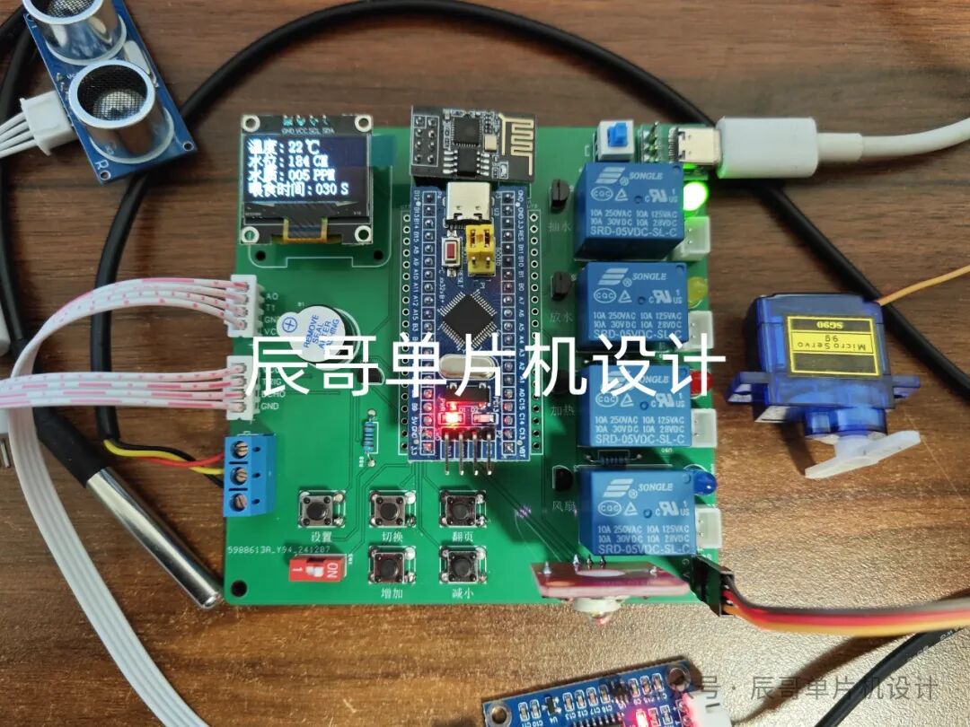
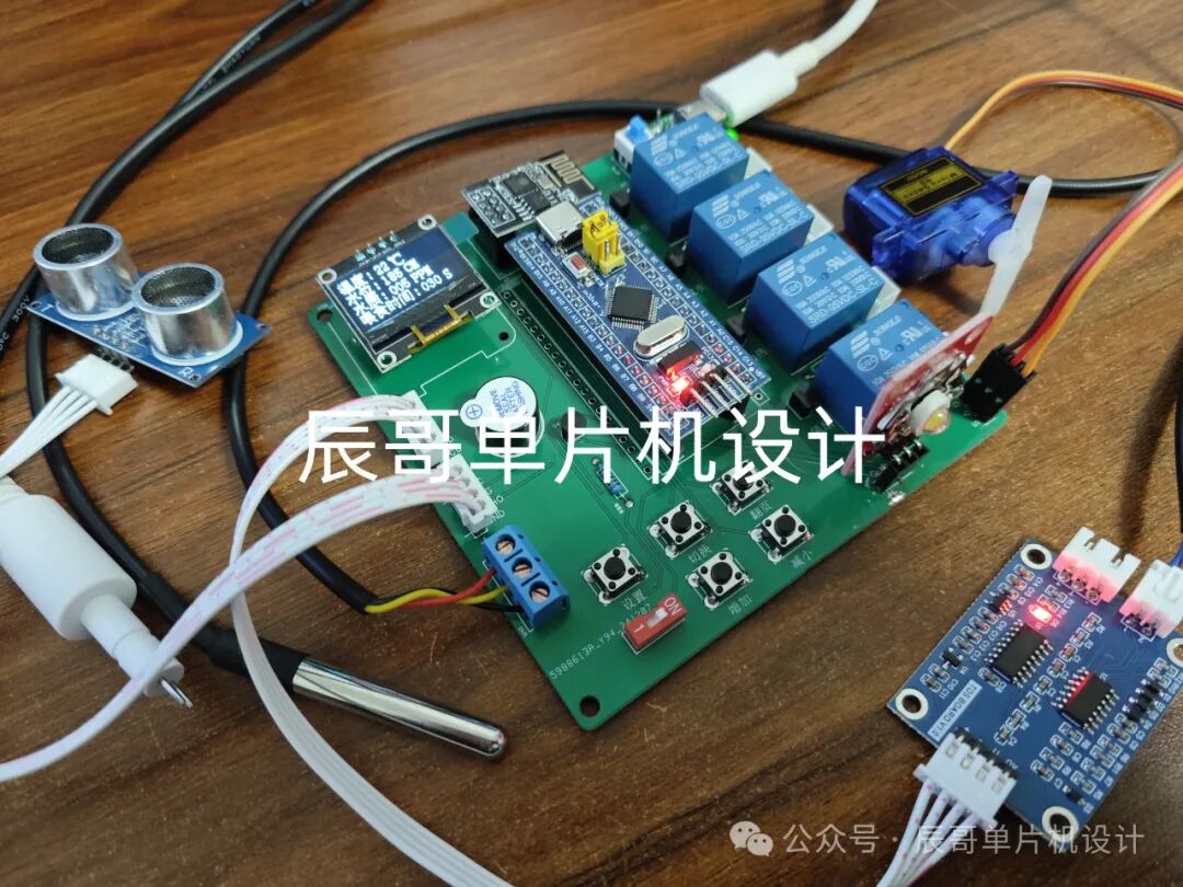
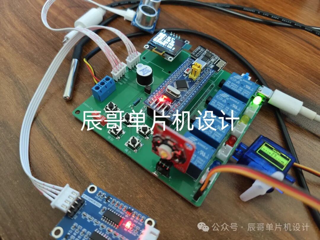
Product images of the project:
Bilibili video link:
https://www.bilibili.com/video/BV1s5qYYAEHh/?share_source=copy_web&vd_source=097fdeaf6b6ecfed8a9ff7119c32faf2
(See the end of the article for data sharing)
01
—
Project Introduction
1. Function Details
STM32 Smart Aquarium/Aquaculture System
The functions are as follows:
-
Can detect temperature, water level, and TDS water quality, while displaying the data on an OLED screen.
-
When the temperature is too high, Relay 1 engages for cooling; when too low, Relay 2 engages for heating. An abnormal condition triggers the buzzer alarm.
-
When the water level is too low, Relay 3 operates to simulate water intake. When the water level is too high, Relay 4 operates to drain water.
-
When TDS water quality is too high, Relays 3 and 4 operate sequentially to simulate water replacement.
-
Can time feeding; after the countdown ends, the servo rotates to simulate feeding operation.
-
Thresholds can be adjusted via buttons.
-
Connects to a mobile app for remote data viewing, LED switch control, threshold adjustments, etc.
2. Bill of Materials
-
STM32F103C8T6 Microcontroller
-
OLED Screen
-
DS18B20 Temperature Sensor
-
ESP8266-01S WiFi Module
-
TDS Conductivity Sensor
-
Ultrasonic Sensor
-
Relay
-
Servo
-
High-Power LED Module
-
Active Buzzer
02
—
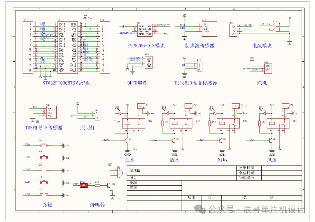
Schematic Design
03
—
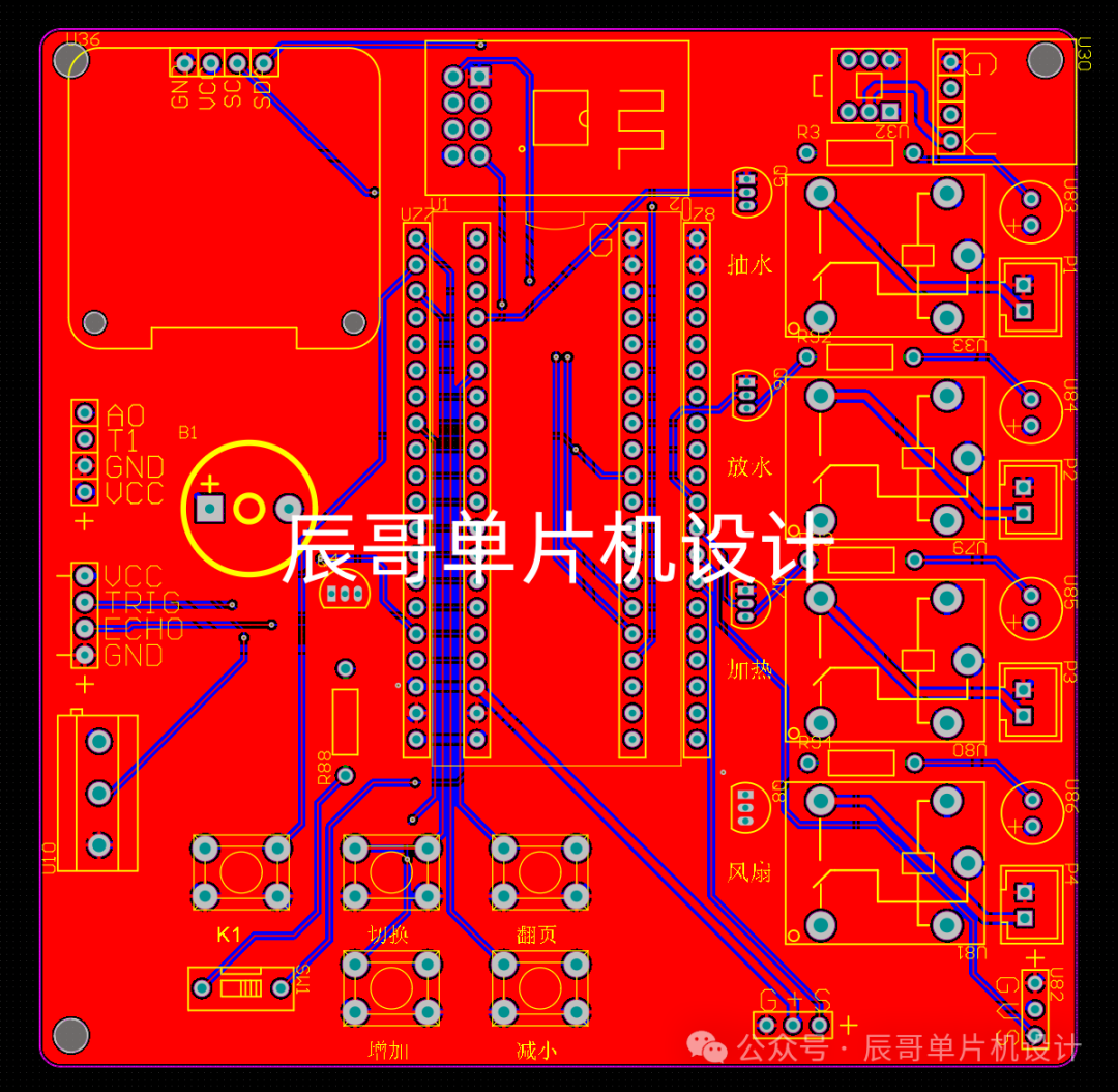
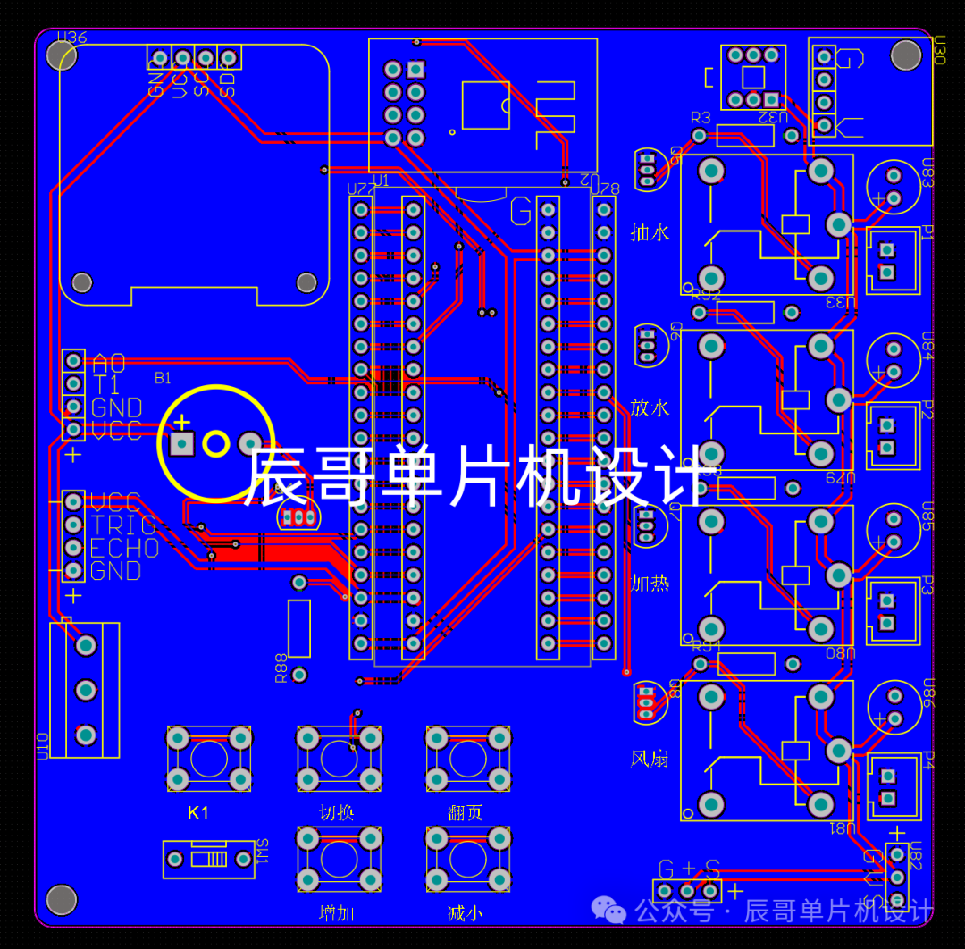
PCB Hardware Design
PCB Diagram
04
—
Program Design
#include "stm32f10x.h"
#include "sys.h"
#include "led.h"
#include "bmp.h"
#include "oled.h"
#include "adc.h"
#include "ds18b20.h"
#include "timer.h"
#include "delay.h"
#include "usart.h"
#include "usart2.h"
#include "cJSON.h"
#include "sr04.h"

int LED_STATUS = 0;
int FAN_STATUS = 0;
char WIFIName[] = "ESP8266-WIFI";
char WIFIpwd[] = "12345678";
int temp_up = 35,temp_down = 15;     // Temperature upper and lower limits
int tds_up = 90,tds_down = 0;      // Water quality upper and lower limits
int level_up = 5,level_down = 60;  // Water level upper and lower limits
int maxHighLevel = 5;                // Maximum water level for replacement
int feedTime = 30;               // Feeding time
int cacheFeedTime = 30;          // Cached feeding time
int sendDataTime = 3;            // Data sending time
int cacheSendTime = 3;           // Cached data sending time

#define LED   PAout(2)     // LED
#define BUZZ  PAout(4)     // Buzzer
#define JD1   PAout(8)      // Relay 1 - Water extraction
#define JD2   PAout(5)      // Relay 2 - Water drainage
#define JD3   PAout(6)      // Relay 3 - Heating
#define JD4   PAout(7)      // Relay 4 - Cooling
#define KEY_EDIT PBin(13)   // Set button
#define KEY_NEXT PBin(14)  // Switch button
#define KEY_SWIT PBin(15)  // Next page button
#define KEY_ADD  PAin(11)  // Increment button
#define KEY_DEC  PBin(12)  // Decrement button
#define TEST PCout(13)
#define SG90_CLOSE  175    // Servo closed
#define SG90_OPEN   185    // Servo opened

// Upper computer data processing
int connectFlag = 0;       // Connection success flag
int handleFlag = 0;        // Flag to determine which data from the upper computer needs processing
int sendFlag = 0;          // Timer time reached, this position indicates sending data
int initFlag = 0;          // ESP8266 initialization success flag
int paramFlag = 1;         // Whether to enable parameter check
int changeWaterFlag = 0;   // Water change flag
int feedFlag = 0;          // Whether to feed
int feedEndFlag = 0;       // Feeding end

unsigned char temp = 0,level = 0; // Temperature, humidity
void paramCheck( void );             // Check if parameters exceed limits
void handleData( void );             // Upper computer data processing
void co2Process(void);               // CO2 data processing
void DisplayUI( void );              // Fixed page UI rendering
void paramEdit( void );              // Threshold parameter setting
void editUiDisplay( int pageIndex ); // Set page UI initialization
void runAlter(int cursor,int count); // Execute parameter modification
extern char *USARTx_RX_BUF;         // Serial data buffer
extern float TDS_value;

int main(void){
	int time;
	delay_init();
	LED_Init();
	OLED_Init();
	Adc_Init();
	DS18B20_Init();
	                  // Temperature initialization
	HC_SR04Config();                  // Ultrasonic initialization
	uart_init(115200);
	timeInit(4999,7199);              // 72M 0.1ms 500ms Serial data initialization,
	timeSendInit(9999,7199);          // 72m 0.1ms 1s    Data sending timer
	timePwmInit(199,7199);            // PWM-> CH3->PA2  CH4->PA3  (Adjust pulse width)
	TIM_SetCompare4(TIM2,100);
	TIM_SetCompare4(TIM2,SG90_CLOSE); // Close feeding
	OLED_ShowChLength(38,16,47,3);    // Displaying startup
		ESP8266Init(WIFIName,WIFIpwd);
	OLED_Clear();
	while(1){
		DisplayUI();
		if( time++ > 5 ){
			time = 0;
			temp  =  getTemperture();           // Get temperature
			delay_ms(1000);
			delay_ms(1000);
			temp  =  getTemperture();           // Get temperature
			TDS_Value_Conversion();             // Get TDS water quality value
		}
		level =  Getlength();         // Get water level
		OLED_ShowNum(45,0,temp,2,16,1);
		OLED_ShowNum(45,16,level,3,16,1);
		OLED_ShowNum(45,32,TDS_value,3,16,1);
		OLED_ShowNum(76,48,cacheFeedTime,3,16,1);
		OLED_Refresh();
		// Start feeding
		if( feedFlag ){
			TIM_SetCompare4(TIM2,SG90_OPEN);
			// Wait for feeding to end
			if( feedEndFlag ){
				feedFlag = 0;
				feedEndFlag = 0;
				feedTime = cacheFeedTime;
				TIM_SetCompare4(TIM2,SG90_CLOSE);
			}
		}
		// Enter settings page
		if( !KEY_EDIT ){
			while( !KEY_EDIT ); // Debounce
			paramEdit();        // Enter parameter settings
			// Refresh parameter prompt button (this button needs to be updated after entering settings)
			if( !paramFlag ) OLED_ShowChLength(105,2,62,1);
			else OLED_ShowString(105,2,"  ",16,1);
		}
		// Switch parameter reminder settings
		if( !KEY_NEXT ){
			while( !KEY_NEXT );
			paramFlag = !paramFlag;
			if( !paramFlag ){
				JD2 = 0;
				JD3 = 0;
				JD4 = 0;
				JD1 = 0;
				BUZZ = 0;
				OLED_ShowChLength(105,2,62,1);
			}else{
				OLED_ShowString(105,2,"  ",16,1);
			}
			OLED_Refresh();
		}
		// Upper computer changes data
		if( handleFlag ) handleData();
		// Upload data every 3 seconds
		if( sendFlag && 1){
			ESP8266Pub(temp,level,TDS_value);
			sendFlag = 0;                 // Reset flag
			sendDataTime = cacheSendTime; // Refresh sending time
		}
		// Check if parameters exceed limits (parameter check enabled)
		if( paramFlag ) paramCheck();
		delay_ms(100);
	}}
05
—
Experimental Results
Data Sharing (Baidu Cloud)
https://pan.baidu.com/s/1ChQKiFGKjoKkRzPhC7Olfw?pwd=vvsy Extraction code: vvsy
(Or scan the QR code below to obtain) For physical purchases, scan the QR code below