unsetunset1. Module Introductionunsetunset
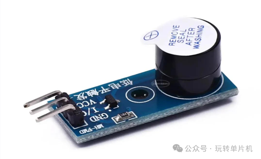
The buzzer is a sound output device commonly used in embedded systems, capable of emitting alert tones or alarms through simple level control. In STM32 development, using a buzzer can achieve functions such as:
- User interaction feedback (e.g., key sound effects)
- Abnormal state alarms (e.g., sensor failure)
- Power-on indication sound
- Sound output examples in teaching experiments
This article takes the STM32F103 series microcontroller as an example to introduce how to use the standard library to drive GPIO to control the buzzer on/off, and explains the development process through practical code examples.
unsetunset2. Hardware Principle Analysisunsetunset
2.1 Working Method of Active Buzzer
Buzzers are divided into active and passive types:
- Active Buzzer: Contains an internal oscillator and can produce sound as long as power is supplied;
- Passive Buzzer: Requires an external frequency signal (e.g., PWM) to produce sound.
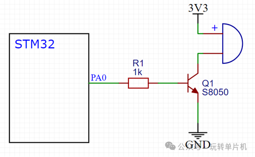
This experiment uses an active buzzer, controlled by active low: When the STM32 outputs a low level, the buzzer sounds; when it outputs a high level, the buzzer stops.
2.2 Circuit Connection Diagram
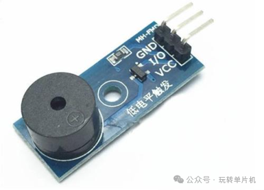
2.3 Physical Diagram
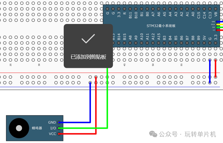
2.4 Wiring Instructions
📌 Wiring Diagram Reserved Area:
| Pin Function | STM32 Pin | Module Pin Description |
|---|---|---|
| Control Pin | PB12 | IN (Signal Input) |
| Power | 3.3V/5V | VCC |
| Ground | GND | GND |
Notes:
- It is recommended to connect a 100~330Ω resistor in series with the control signal line to limit current;
- A 104 capacitor can be connected in parallel for filtering to enhance stability;
- The control pin is recommended to use GPIO push-pull output mode.
unsetunset3. Software Implementation and Standard Library Code Explanationunsetunset
3.1 Header File Inclusion
#include "stm32f10x.h"   // Include STM32 standard library header file
#include "Delay.h"       // Delay function header file (must be implemented in advance)
Notes:
<span>stm32f10x.h</span>contains register definitions and peripheral control structures;<span>Delay.h</span>encapsulates millisecond delay functions, used in the main loop to control the duration of buzzer sound on/off.
3.2 Initialize GPIO to Control the Buzzer
void Buzzer_Init(void) {
    // 1. Enable GPIOB peripheral clock, otherwise subsequent GPIO operations will be invalid
    RCC_APB2PeriphClockCmd(RCC_APB2Periph_GPIOB, ENABLE);

    // 2. Configure PB12 as push-pull output
    GPIO_InitTypeDef GPIO_InitStructure;                   // Define GPIO initialization structure
    GPIO_InitStructure.GPIO_Mode = GPIO_Mode_Out_PP;       // Set to push-pull output mode
    GPIO_InitStructure.GPIO_Pin = GPIO_Pin_12;             // Specify using PB12 pin
    GPIO_InitStructure.GPIO_Speed = GPIO_Speed_50MHz;      // Set output speed to 50MHz

    GPIO_Init(GPIOB, &GPIO_InitStructure);                 // Apply configuration to initialize PB12
}
Notes:
- Push-pull output can directly drive the buzzer module;
- The GPIO clock must be enabled, otherwise initialization will be invalid;
- It is recommended to use high-speed output to ensure timely control response.
3.3 Control Buzzer On/Off Functions
void Buzzer_On(void) {
    GPIO_ResetBits(GPIOB, GPIO_Pin_12);  // Set pin to low level, active buzzer starts to sound
}

void Buzzer_Off(void) {
    GPIO_SetBits(GPIOB, GPIO_Pin_12);    // Set pin to high level, buzzer stops sounding
}
Notes:
<span>GPIO_ResetBits()</span>indicates setting the pin output to low level;<span>GPIO_SetBits()</span>indicates setting the pin output to high level;- This module is active low, meaning low level sounds, high level stops.
3.4 Main Function Loop Control Example
int main(void)
{
    Buzzer_Init(); // Initialize buzzer control pin

    while (1)
    {
        Buzzer_On();     // Buzzer sounds
        Delay_ms(100);   // Delay 100ms

        Buzzer_Off();    // Buzzer stops
        Delay_ms(100);   // Delay 100ms

        Buzzer_On();     // Sound again
        Delay_ms(100);   // Delay 100ms

        Buzzer_Off();    // Stop sounding
        Delay_ms(700);   // Delay 700ms to create rhythm
    }
}
Notes:
- Use delay function to control the interval of buzzer sound;
- By modifying the delay parameters, different rhythmic alert tones can be created;
- In practical applications, the buzzer can be triggered in conjunction with sensor or button states.
unsetunset4. Function Expansion Suggestionsunsetunset
| Function Expansion | Implementation Description |
|---|---|
| Status Alarm | Sound alarm after determining threshold with sensors (e.g., smoke alarm) |
| Button Feedback | Emit a short beep when the user presses a button to enhance interaction experience |
| Sound Rhythm | Adjust the combination of sound and delay parameters for different rhythms |
| PWM Control Tone | For passive buzzers, PWM can be generated using TIM to control |
unsetunset5. Debugging Suggestions and Common Issuesunsetunset
| Issue Phenomenon | Cause Investigation and Solution Suggestions |
|---|---|
| Buzzer silent | Check if GPIO outputs low level, whether the circuit is reversed |
| Buzzer continuously sounds | Program did not pull high level in time or is stuck in a dead loop |
| Compilation error | Check if header files are correctly included / macro definitions are enabled |
| Delay ineffective or error | <span>Delay.h</span> whether the millisecond delay function is correctly implemented |
| Program download unresponsive | Check if power is reversed / voltage is insufficient / BOOT setting is incorrect |
unsetunset6. Practical Tipsunsetunset
- It is recommended to encapsulate the buzzer control logic into function modules for easy calling;
- Can be linked with LED display and serial debugging to form a complete alert system;
- If using a passive buzzer later, PWM output from a timer is required to control different frequencies for tone.
unsetunset7. Conclusionunsetunset
The buzzer module is one of the most basic and intuitive modules in STM32 peripheral learning. By controlling high and low levels through GPIO, sound on/off control can be easily achieved, making it very suitable for novice teaching, system debugging, and functional prompts.
Mastering the control method of the buzzer module not only helps to build a complete interactive system, but also lays a solid foundation for subsequent developments such as button feedback, abnormal alarms, and timed prompts.