The article about the module is about to begin, and I plan to write a series of beginner and intermediate tutorials on modules and STM32 in the future.
Generally speaking, manufacturers of the ESP8266 module will periodically upgrade the firmware inside the module and release it, so we must also master the method of upgrading the firmware of the ESP8266 module. This article demonstrates how to perform a local firmware upgrade based on the Anxinke ESP8266 module WiFi module (Note: this article is aimed at ESP8266-12F, applicable to 12S, other modules have not been tested).
First, let’s take a look at the current firmware version of the 8266 module, as shown below.

1. Download Mode
ESP8266 has different modes: running mode, download mode, and test mode. To enter download mode, refer to the configuration below:
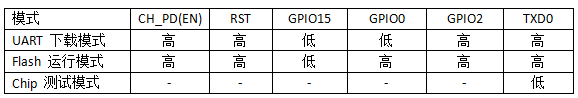
The operating state of the ESP32 is mainly determined by GPIO0:
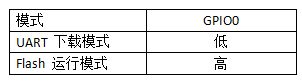
In summary, the first thing we need to do is ensure that the ESP8266 enters download mode.
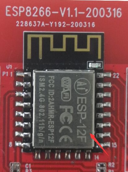
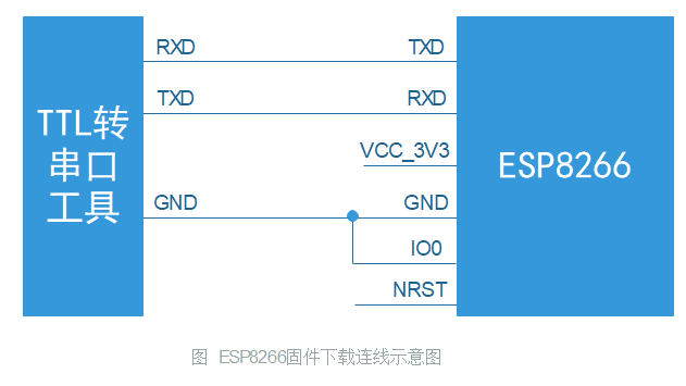
We will connect the TTL to serial tool to the ESP8266 WiFi module pins as shown in the figure below:
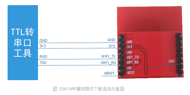
The actual connection of my 8266 module is as follows (I connected IO0 directly to the module’s GND pin, which is intended to pull down IO0):
After connecting the module to the TTL serial tool, insert the TTL serial tool into the computer’s USB port.
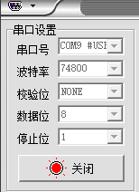
Open the serial debugging assistant, set the baud rate to 74800, as shown in the figure below:
Power on the 8266 module again (my module can touch NRST and GND for more than 200 milliseconds without needing to power on again), the serial assistant prints the following content:
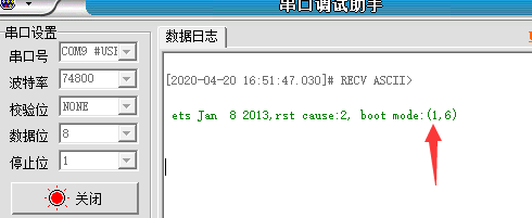
Here we only need to pay attention to the content in parentheses after boot mode (1,6). When the first number is 1, it indicates that we have entered download mode, and the following numbers can be ignored.
Once we confirm that we have entered download mode, we can close the serial debugging assistant software.

2. Firmware Burning
This time, the firmware version I am burning is 1.7.2.0, and the burning tool used is flash_download_tools. Both files can be obtained directly from the QQ group 940556740 or downloaded from the Anxinke official website.
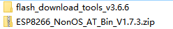
Figure: Files required for burning
Enter the flash_download_tools_v3.6.6 folder, double-click , to open the firmware burning tool.
The software runs and pops up the following interface
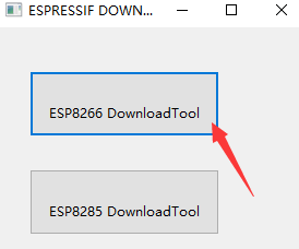
Click the ESP8266 DownloadTool button pointed to by the arrow.
The following interface pops up
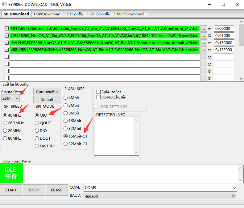
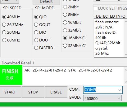
Select the four required firmware files (note that user1.2048.new.5.bin is from the at directory, not the at_sdio directory), configure the parameters as indicated by the arrow, and set the baud rate to 460800.
(Note: This actually involves a lot of knowledge points, to demonstrate the complete process, I will write it out directly, and in the later part of this article, I will discuss some questions or knowledge points)
After configuring the parameters, click the button , and the following prompt will appear:
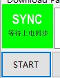
Power on the ESP8266 module again
The firmware burning is completed quickly.

3. Verify Firmware Version
After the firmware burning is completed, we can leave IO0 floating, set the baud rate of the serial debugging assistant to 115200, and power the module again, as shown in the printed output:
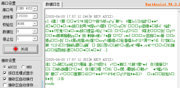
The startup will eventually output ready, and the garbled characters are the information output by the module at baud rate 74800.
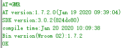
Execute the command AT+GMR to check the current firmware version
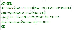
You can see that the current firmware version information is:
AT version:1.7.3.0(Mar 19 2020 18:15:04)SDK version:3.0.3(8427744)compile time:Mar 24 2020 16:16:12Bin version(Wroom 02):3.0.3Where 1.7.3.0 is the firmware version we burned.
At this point, we have completed the process of burning the firmware version, but in fact, there are many questions that have not been addressed, so let’s discuss them below.

4. Q&A Collection
Q: How to determine the Flash size of the ESP8266 module you are using?
A: We can refer to the following ESP8266 option table to find the Flash size corresponding to our module model.
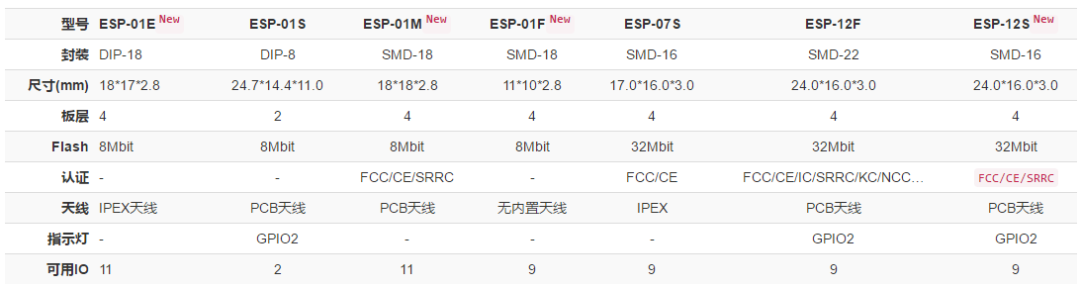
Figure: ESP8266 module selection table (Source: Anxinke)
For example, my module uses ESP-12F, so I can find that the Flash size is 32Mbit.
Q: How to choose CrystalFreq in the ESP8266 download tool?
A: In CrystalFreq, we use the clock of the module. I have the ESP-12F module, and according to its schematic, it uses a 26MHz crystal, as shown below:
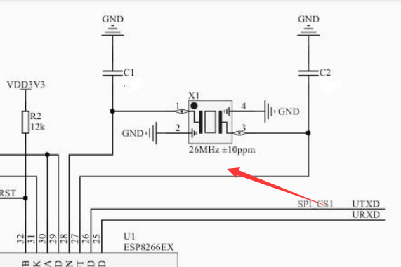
Figure: ESP-12F schematic crystal part
So I selected 26MHz in the tool for CrystalFreq.
Q: My Flash is 32Mbit, why should I choose 16Mbit-C1 in the software?
A: First, let’s take a look at what FLASH SIZE means in the tool. There is a Readme.pdf file in the root directory of the download tool, as shown in the image below.
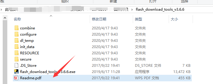
Open that file, and let’s look at the explanation about FlashSize in the file, as shown below:
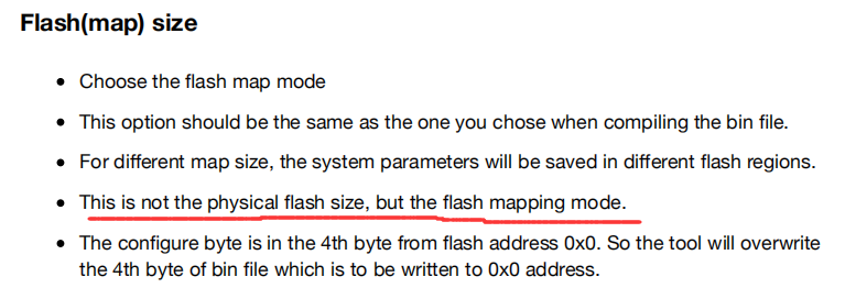
Pay attention to the part I marked with a red line: “This option does not represent the actual physical memory of the Flash being used, but rather the mapping mode of the Flash“. How should this be understood? Let’s not explain it yet; let’s look at what FLASH SIZE options mean (hover your mouse over the option to see what hints appear  ).
).
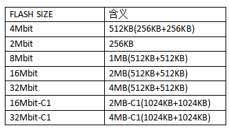
We organize the information from the above image and get the following table:

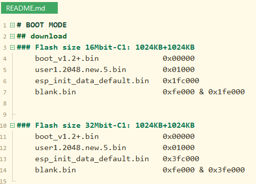
At this point, I can explain. According to the README in the at directory of the firmware folder we downloaded, as shown below:
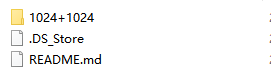
We can see that we are using 1024+1024, which means that in the DOWNLOAD TOOL software, we should choose at least the option ending with C1, so we are left with the options of 16Mbit-C1 and 32Mbit-C1. So how do we eliminate these two options?
My module’s Flash physical size is 32Mbit, shouldn’t I choose 32Mbit-C1? You got half of it right because I thought the same way at first.
When I chose 32Mbit-C1 for downloading, although the download was successful, when the module powered on again, the output information was as follows:
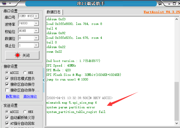
There was an error message in the output indicating a system partition error, and the partition table registration failed:
mismatch map 5,spi_size_map 6system param partition errorsystem_partition_table_regist failWTF?? After searching online, I found out that to burn firmware 1.7 to ESP-12F, you need to use the 16Mbit mode for burning (at that time, many horses were galloping in my heart).
Based on the above, I can only choose 16Mbit-C1. In fact, if you have a basic understanding of SDK development, it should be understandable. But I think those reading this article have just started with ESP, so I won’t explain it in detail, just leaving a hint.
Q: What is the difference between 32Mbit and 32Mbit-C1 in the ESP8266 download tool?
A: This question has already been answered above.
Q: How to choose SPI MODE in the download tool?
A: First, the “ESP8266EX Technical Specification” describes the external FLASH, as shown in the image below:
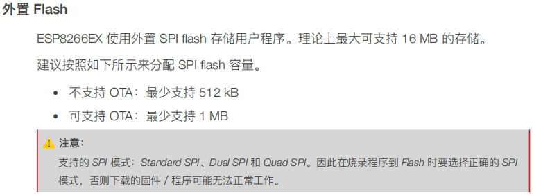
From the above image, it can be seen that the ESP8266 chip supports Standard SPI, Dual SPI, and Quad SPI. What is the difference between these modes? In summary, it’s just the difference in read and write speed.
Let’s take a look at the definitions of these three SPI interfaces:
Standard SPI: CLK, /CS, DI, DO, /WP, /HoldDual SPI: CLK, /CS, IO0, IO1, /WP, /HoldQuad SPI: CLK, /CS, IO0, IO1, IO2, IO3As far as I know, some friends using ESP8266 do not understand SPI. It’s okay; you can judge based on the schematic of the module you are using. For example, in my case of the 12F:
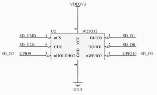
Figure: External Flash of ESP-12F
Combining the above image and the number of pins required for the three SPI interfaces, it can be concluded that all three SPI interfaces used in my 12F are supported. Therefore, to achieve faster speeds, I chose the QIO mode. (This part I have explained very generally; if I want to explain it clearly, I estimate I would have to write a separate article to explain it.)
Q: How should the file selection and address configuration during burning be filled out?
A: You can directly check the Readme in the firmware folder to know how to fill it out. For example, the Readme in my burning firmware folder:
Q: What if I select the wrong options during firmware burning?
A: No problem; at most, the firmware will not work properly, and you can just switch to another option for burning.

5. Extra Extra
The blogger is currently making his own board, and the products currently for sale include the STM32L431 minimum core board and the WiFi module. In the future, NB modules, 4G modules, and other communication modules, as well as IoT learning kits, will be launched.

The case of connecting the minimum core board and the WiFi module to oneNET and controlling it through a mini program has been prepared. If your friends need it, feel free to recommend it. Thank you! If you become my customer, let me pamper you.