Click the blue text above: IoT Inn
Serial communication plays a very important role in embedded development. It is often used to debug systems, print necessary debugging information, and help us analyze and locate problems. Many common peripherals also support serial protocols, such as WIFI modules, Bluetooth modules, 4G modules, fingerprint modules, PM2.5 sensors, formaldehyde sensors, and many other components. In this section, we will officially learn about the serial communication of the STM32 microcontroller.
1Introduction to STM32 IoT Kit
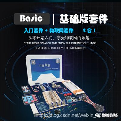
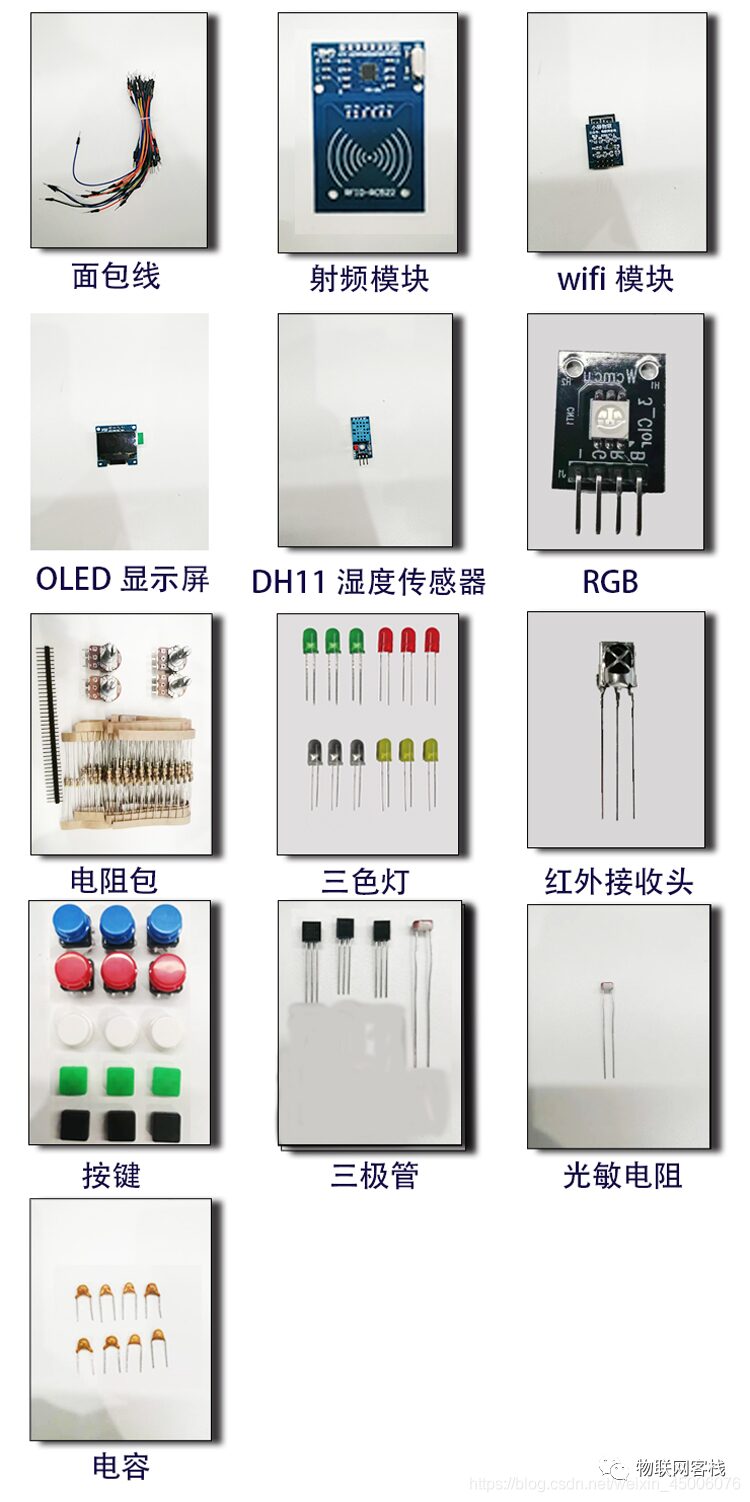
The STM32 IoT Kit currently has two versions: Basic and Advanced. Future versions will include application and voice versions. The core board uses the STM32F103C8T6 core board. The main components of the basic version are as follows:
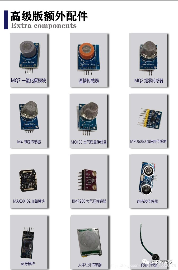
The main components of the advanced version are as follows:
The STM32 IoT Kit aims to help everyone get started with the Internet of Things (IoT). You will not only learn about STM32 but also understand the development of WeChat Mini Programs and IoT server backend development, truly grasping all aspects of an IoT project. Based on this, we have customized a general WIFI communication protocol (which can be understood as similar to AT commands, but with higher integration; only a few commands can directly connect to the cloud platform), such as three commands to connect to Tencent Cloud instances.
In the future, we will continue to add support for mainstream cloud platforms such as Tuya Smart, Telecom Cloud, Mobile Onenet, and Alibaba Cloud, striving for a set of STM32 code that can connect to different cloud platforms through customized WIFI modules. Friends with product development needs are welcome to contact us for consultation and customized IoT solutions!
This IoT kit can support college students participating in IoT-related competitions, applying for school innovation projects, and completing graduation designs. Our positioning is to be an open-source smart hardware service provider, exploring IoT together with everyone. Our mission is to promote the implementation and popularization of more IoT products, making technology no longer a barrier!
2 Introduction to Communication Methods
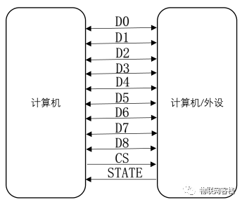
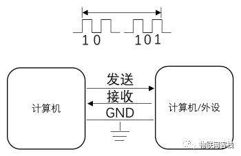
The communication method used by the serial port is serial communication. Serial communication is in contrast to parallel communication, where data bits are transmitted simultaneously. Its characteristics include high transmission speed and efficiency, but it uses more data lines and has higher transmission costs, making it suitable for short-distance communication. The schematic diagram is as follows:
Serial communication refers to data being transmitted one bit at a time through a single data line to the target device. Its characteristics are that it requires at least one transmission line to complete, is low-cost but has slower transmission speed, and only requires a few lines to exchange information between systems. The schematic diagram is as follows:
3Serial Communication Protocols
According to the direction of data transmission, it can be divided into three main types: simplex, half-duplex, and full-duplex.
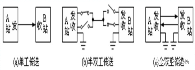
(a) Simplex Protocol
Data can only be transmitted from one device to another, unidirectional transmission.
(b) Half-Duplex Protocol
Data transmission between devices is bidirectional, but at the same time, only one direction can transmit data, and the receiving switch can be controlled by software.
(c) Full-Duplex Protocol
Data can be sent and received simultaneously between devices at any time.
4Introduction to STM32 Serial Port
The STM32F103C8T6 has three USARTs: USART1, USART2, and USART3. USART (Universal Synchronous Asynchronous Receiver Transmitter) is a serial communication device that can be configured in synchronous and asynchronous modes.
Generally, a microcontroller also has a UART, which is a trimmed version of USART that only supports asynchronous communication. The difference is that synchronous communication requires a clock line to provide the clock. The serial communication we usually use is basically UART.
(1) Common Uses of Serial Ports
a. Print system debugging logs to quickly locate problems.
b. Control serial devices.
c. Control industrial communication devices through RS232/RS485, etc.
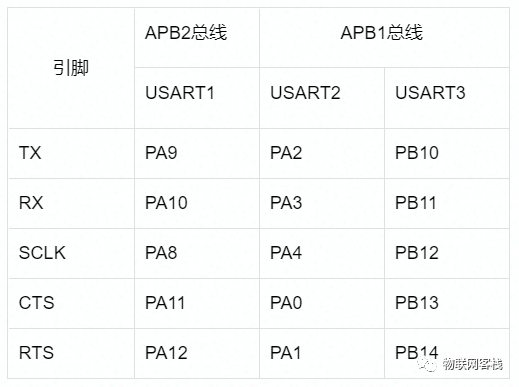
(2) STM32F103C8T6 Serial Port Resources
5Hardware Design
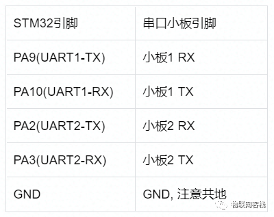
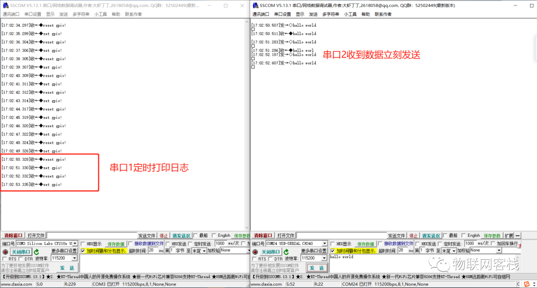
This serial communication experiment uses Serial Port 1 and Serial Port 2, where Serial Port 1 is used to download programs and print system logs. Serial Port 2 immediately returns data received in interrupt mode. The connection method is as follows:
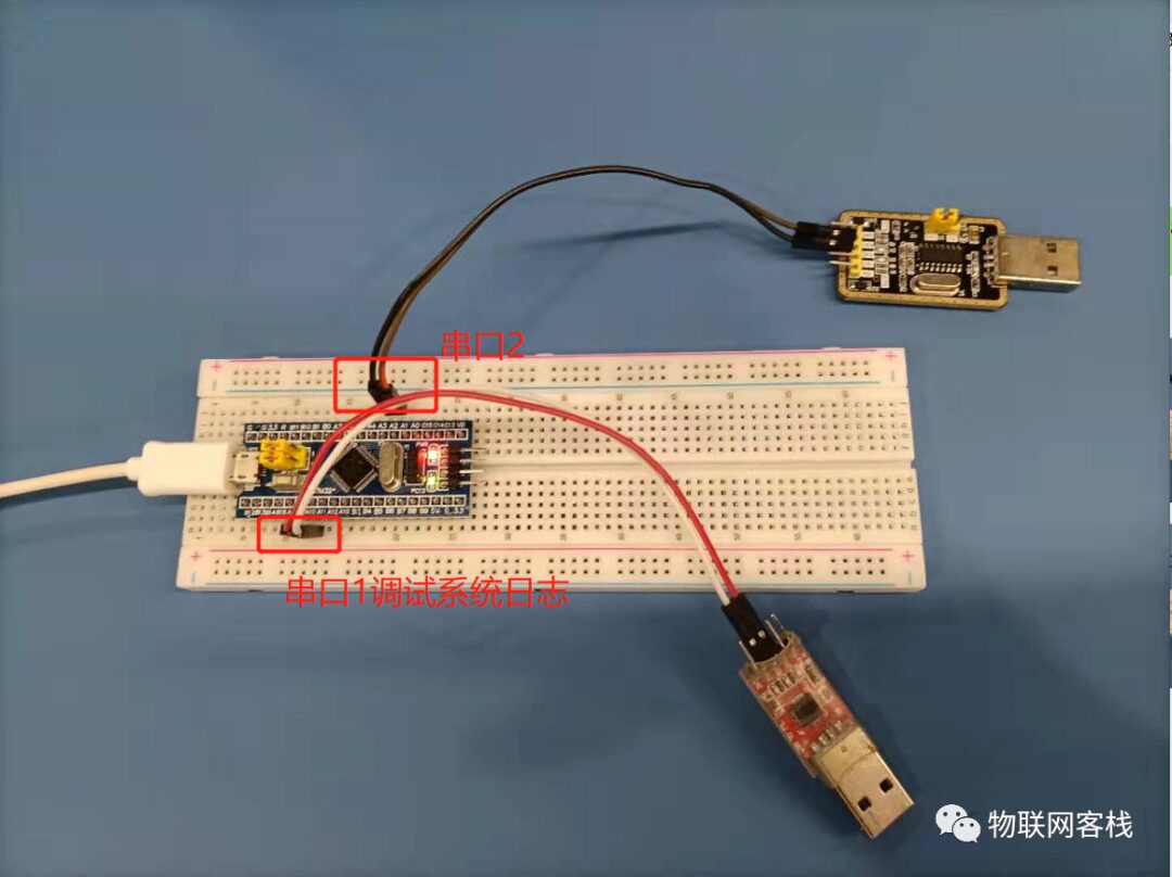
The physical diagram is as follows:
1Create New Project
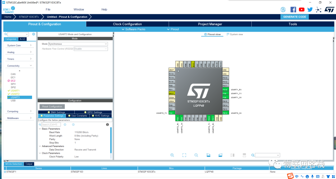
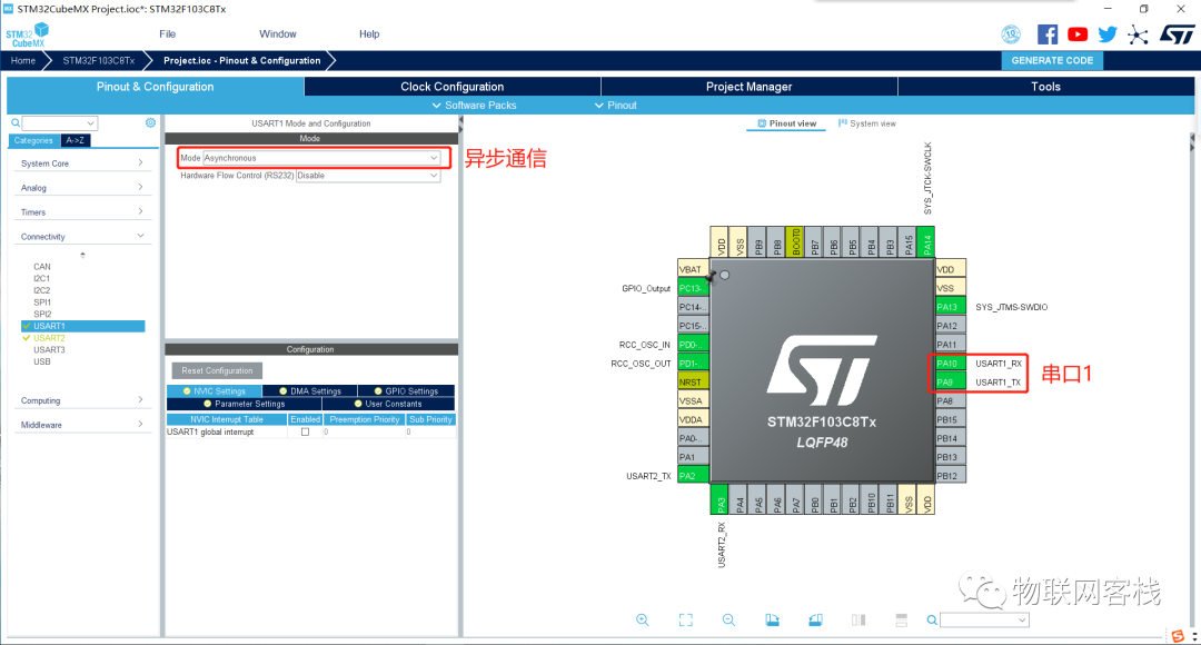
Use STM32CubeMX to create a new project, configure the RCC and PC13 pin output according to the environment setup chapter, enable Serial Port 1, and select asynchronous communication mode.
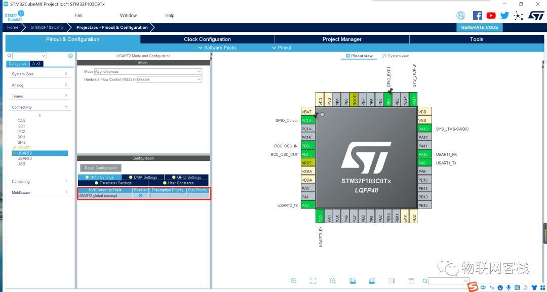
Enable Serial Port 2 and configure interrupts simultaneously.
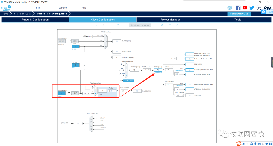
Enter the Clock configuration page, select HSE clock source, and after frequency multiplication, the main clock is 72MHz.
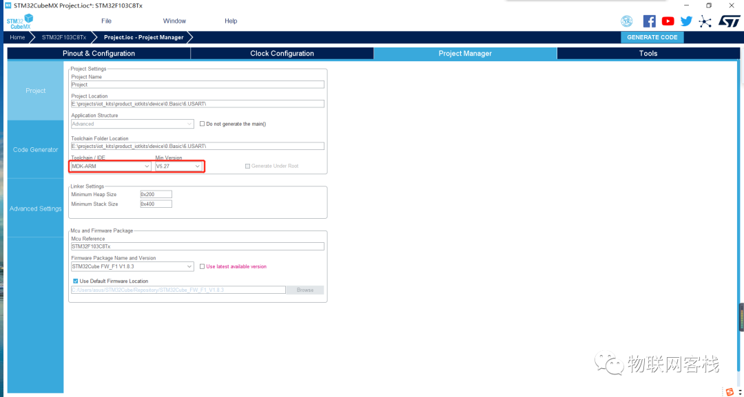
Switch to the Project Manager section, set the project name, project save directory, toolchain, and other information. The parameters are as shown in the following figure.
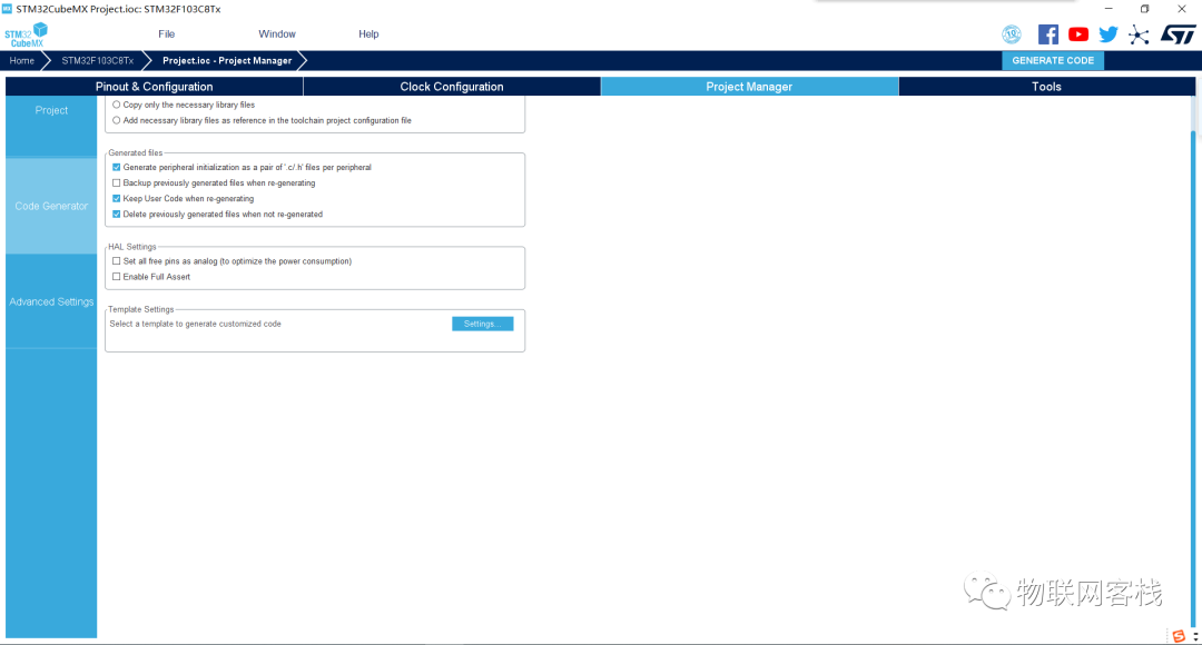
Click the left column Code Generator, then check Generate peripheral initialization as a pair of ‘.c/.h’ files per peripheral. By checking this option, peripherals will be saved in separate files instead of all in main.c.
Click the GENERATE button to generate a new project.
2Function Description
First, let’s look at the serial port initialization function. Serial Port 1 and Serial Port 2 have the same configuration: 115200 baud rate, 8-bit word length, one stop bit, no parity, and no flow control.
void MX_USART1_UART_Init(void){ huart1.Instance = USART1; huart1.Init.BaudRate = 115200; huart1.Init.WordLength = UART_WORDLENGTH_8B; huart1.Init.StopBits = UART_STOPBITS_1; huart1.Init.Parity = UART_PARITY_NONE; huart1.Init.Mode = UART_MODE_TX_RX; huart1.Init.HwFlowCtl = UART_HWCONTROL_NONE; huart1.Init.OverSampling = UART_OVERSAMPLING_16; if (HAL_UART_Init(&huart1) != HAL_OK) { Error_Handler(); }} /* USART2 init function */ void MX_USART2_UART_Init(void){ huart2.Instance = USART2; huart2.Init.BaudRate = 115200; huart2.Init.WordLength = UART_WORDLENGTH_8B; huart2.Init.StopBits = UART_STOPBITS_1; huart2.Init.Parity = UART_PARITY_NONE; huart2.Init.Mode = UART_MODE_TX_RX; huart2.Init.HwFlowCtl = UART_HWCONTROL_NONE; huart2.Init.OverSampling = UART_OVERSAMPLING_16; if (HAL_UART_Init(&huart2) != HAL_OK) { Error_Handler(); }} void HAL_UART_MspInit(UART_HandleTypeDef* uartHandle){ GPIO_InitTypeDef GPIO_InitStruct = {0}; if(uartHandle->Instance==USART1) { /* USER CODE BEGIN USART1_MspInit 0 */ /* USER CODE END USART1_MspInit 0 */ /* USART1 clock enable */ __HAL_RCC_USART1_CLK_ENABLE(); __HAL_RCC_GPIOA_CLK_ENABLE(); /**USART1 GPIO Configuration PA9 ------> USART1_TX PA10 ------> USART1_RX */ GPIO_InitStruct.Pin = GPIO_PIN_9; GPIO_InitStruct.Mode = GPIO_MODE_AF_PP; GPIO_InitStruct.Speed = GPIO_SPEED_FREQ_HIGH; HAL_GPIO_Init(GPIOA, &GPIO_InitStruct); GPIO_InitStruct.Pin = GPIO_PIN_10; GPIO_InitStruct.Mode = GPIO_MODE_INPUT; GPIO_InitStruct.Pull = GPIO_NOPULL; HAL_GPIO_Init(GPIOA, &GPIO_InitStruct); /* USER CODE BEGIN USART1_MspInit 1 */ /* USER CODE END USART1_MspInit 1 */ } else if(uartHandle->Instance==USART2) { /* USER CODE BEGIN USART2_MspInit 0 */ /* USER CODE END USART2_MspInit 0 */ /* USART2 clock enable */ __HAL_RCC_USART2_CLK_ENABLE(); __HAL_RCC_GPIOA_CLK_ENABLE(); /**USART2 GPIO Configuration PA2 ------> USART2_TX PA3 ------> USART2_RX */ GPIO_InitStruct.Pin = GPIO_PIN_2; GPIO_InitStruct.Mode = GPIO_MODE_AF_PP; GPIO_InitStruct.Speed = GPIO_SPEED_FREQ_HIGH; HAL_GPIO_Init(GPIOA, &GPIO_InitStruct); GPIO_InitStruct.Pin = GPIO_PIN_3; GPIO_InitStruct.Mode = GPIO_MODE_INPUT; GPIO_InitStruct.Pull = GPIO_NOPULL; HAL_GPIO_Init(GPIOA, &GPIO_InitStruct); /* USART2 interrupt Init */ HAL_NVIC_SetPriority(USART2_IRQn, 0, 0); HAL_NVIC_EnableIRQ(USART2_IRQn); /* USER CODE BEGIN USART2_MspInit 1 */ /* USER CODE END USART2_MspInit 1 */ }} This function configures the RCC clock and GPIO pins during the initialization of the serial port. For Serial Port 2, it also adds interrupt configuration functionality.
3Modify Program
(1) First redefine the printf function
To redirect printf output to the serial port, you need to point the output in the fputc function to the serial port (redirecting). The method is simple; just implement this function in the Keil project. Note that you need to include the header file #include “stdio.h”; otherwise, FILE will not be recognized.
int fputc(int ch, FILE *f){ HAL_UART_Transmit(&huart1, (uint8_t *)&ch, 1, 0xFFFF); return ch;} When writing code, it is often necessary to consider system compatibility and add compatibility processing for the GNU compilation system. The modification is as follows:
#ifdef __GNUC__ /* With GCC/RAISONANCE, small printf (option LD Linker->Libraries->Small printf set to 'Yes') calls __io_putchar() */ #define PUTCHAR_PROTOTYPE int __io_putchar(int ch) #else #define PUTCHAR_PROTOTYPE int fputc(int ch, FILE *f) #endif /* __GNUC__ */ /** * @brief Retargets the C library printf function to the USART. * @param None * @retval None */ PUTCHAR_PROTOTYPE{ /* Place your implementation of fputc here */ /* e.g. write a character to the EVAL_COM1 and Loop until the end of transmission */ HAL_UART_Transmit(&huart1, (uint8_t *)&ch, 1, 0xFFFF); return ch;} uint8_t aRxBuffer; void HAL_UART_RxCpltCallback(UART_HandleTypeDef *huart){ /* Prevent unused argument(s) compilation warning */ UNUSED(huart); /* NOTE: This function should not be modified, when the callback is needed, the HAL_UART_RxCpltCallback could be implemented in the user file */ if (huart->Instance == USART2) { HAL_UART_Transmit(&huart2, &aRxBuffer, 1, 100); // Immediately send back received data HAL_UART_Receive_IT(&huart2, &aRxBuffer, 1); // Re-enable serial port receive interrupt }} Note that in the GNU compilation system, to implement printf redirection, you need to use the __io_putchar(int ch) function. To maintain program compatibility, the macro definition PUTCHAR_PROTOTYPE is added.
(2) Then complete the serial send and receive processing
a. Rewrite the HAL_UART_RxCpltCallback function in the usart.c file for the serial port receive complete callback function.
uint8_t aRxBuffer; void HAL_UART_RxCpltCallback(UART_HandleTypeDef *huart){ if (huart->Instance == USART2) { HAL_UART_Transmit(&huart2, &aRxBuffer, 1, 100); HAL_UART_Receive_IT(&huart2, &aRxBuffer, 1); }} Note that in this function, HAL_UART_Transmit is the serial send function. The above implementation immediately sends back the received data, and HAL_UART_Receive_IT function re-enables the serial port receive interrupt.
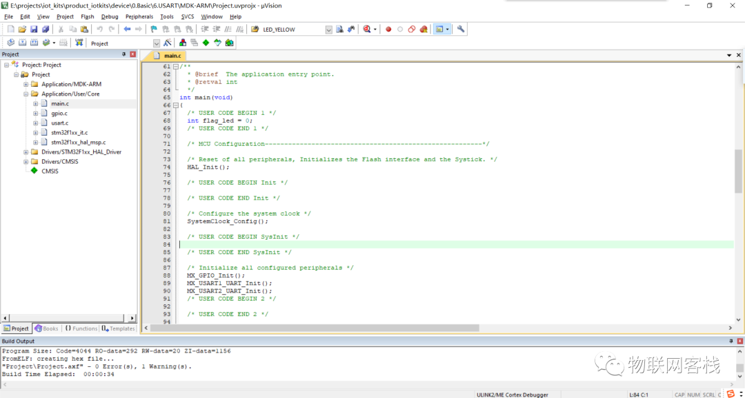
b. In the main.c file, printf periodically prints system logs.
extern uint8_t aRxBuffer; int main(void){/* USER CODE BEGIN 1 */int flag_led = 0;/* USER CODE END 1 */ /* MCU Configuration--------------------------------------------------------*/ /* Reset of all peripherals, Initializes the Flash interface and the Systick. */HAL_Init(); /* USER CODE BEGIN Init */ /* USER CODE END Init */ /* Configure the system clock */SystemClock_Config(); /* USER CODE BEGIN SysInit */ /* USER CODE END SysInit */ /* Initialize all configured peripherals */MX_GPIO_Init();MX_USART1_UART_Init();MX_USART2_UART_Init();/* USER CODE BEGIN 2 */HAL_UART_Receive_IT(&huart2,&aRxBuffer,1);/* USER CODE END 2 */ /* Infinite loop */ /* USER CODE BEGIN WHILE */while (1){/* USER CODE END WHILE */ /* USER CODE BEGIN 3 */HAL_GPIO_WritePin(GPIOC, GPIO_PIN_13, GPIO_PIN_RESET);printf("reset gpio!\r\n");HAL_Delay(1000);HAL_GPIO_WritePin(GPIOC, GPIO_PIN_13, GPIO_PIN_SET);printf("set gpio!\r\n");HAL_Delay(1000); }/* USER CODE END 3 */} First, enable the serial port receive function, and then you can call the printf function. Note to include the header file #include”stdio.h”.
According to the method in the previous section, download the program to the core board, and you can see that the system normally prints debugging logs. By sending data to Serial Port 2 from the host computer, you can also immediately receive return messages.
QQ Group: 906015840 (Note: IoT Project Communication)
Forum Communication: http://bbs.xiaoyiiot.cn/
Source Code Retrieval: Reply xiaoyi_stm32kits in the public account
Hardware Retrieval: Search for “Xiao Yi IoT” on Taobao
Hardware Retrieval via Mini Program: Click me
Produced by Xiao Yi IoT: Only those who lie forever in the mud will not fall into the pit again. – Hegel