For STM32, from previous learning, we can know that STM32 refers to the 32-bit microcontroller developed by STMicroelectronics.
Today we will learn about the EXTI of STM32.
1. Introduction to EXTI
EXTI (External interrupt/event controller) manages the 20 interrupt or event lines of the controller. Each interrupt or event line corresponds to an edge detector, which can detect the rising and falling edges of input signals. EXTI can be configured individually for each interrupt or event line, allowing it to be set as either an interrupt or an event, as well as the properties of the triggering event.
2. EXTI Functional Block Diagram and Principles
The functional block diagram of EXTI contains the core content of EXTI. Mastering the functional block diagram gives a comprehensive understanding of EXTI, making programming thoughts very clear. The EXTI functional block diagram is as follows:
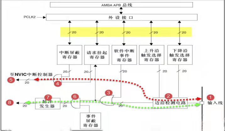
In the diagram, many signal lines are marked with a slash and labeled with the number “20”, indicating that there are 20 similar signal lines inside the controller, which matches the total of 20 interrupt/event lines in EXTI. Therefore, as long as we understand the principle of one line, we also know the principles of the other 19 lines. EXTI can be divided into two main functional parts: one is to generate interrupts, and the other is to generate events, which differ from a hardware perspective.
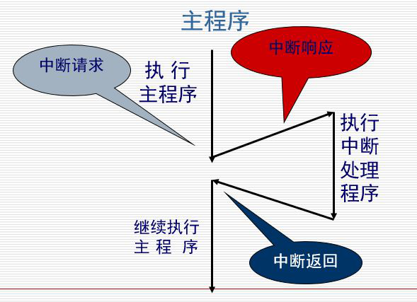
First, let’s look at the circuit flow indicated by the red dashed line in the diagram. It is a line that generates interrupts, and the final signal flows into the NVIC controller.
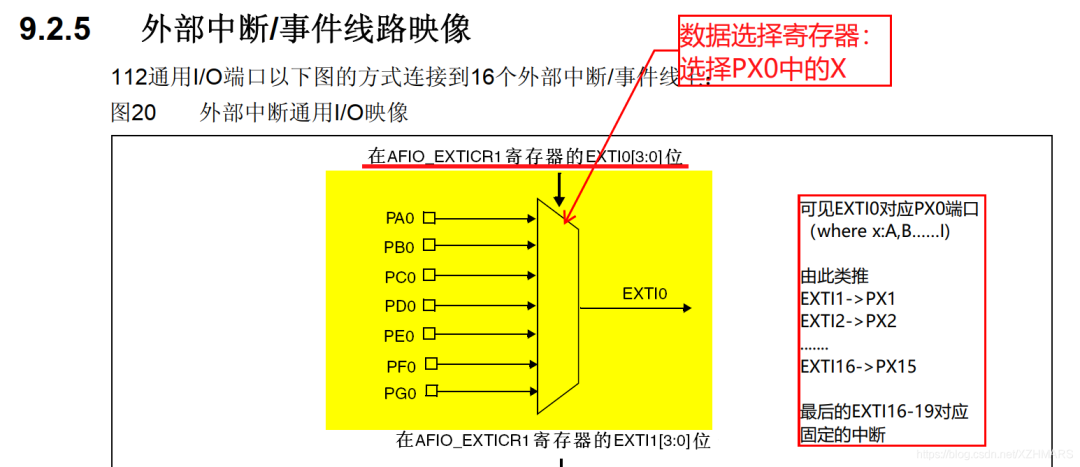
Number 1 is the input line. The EXTI controller has 19 interrupt/event input lines, which can be set to any GPIO or some peripheral events through registers. This part will be explained in detail later. Input lines generally have signal level changes.
Number 2 is an edge detection circuit. It triggers the selection register for rising edges (EXTI_RTSR) and the selection register for falling edges (EXTI_FTSR) based on the settings of the corresponding bits to control signal triggering. The edge detection circuit takes the input line as the signal input. If it detects an edge change, it outputs a valid signal of 1 to number 3 circuit; otherwise, it outputs an invalid signal of 0. The EXTI_RTSR and EXTI_FTSR registers can control which type of level transition processes need to be detected, which can be rising edge only, falling edge only, or both rising and falling edges.
Number 3 circuit is actually an OR gate circuit. One input comes from number 2 circuit, and the other input comes from the software interrupt event register (EXTI_SWIER). EXTI_SWIER allows us to start the interrupt/event line through program control, which is very useful in certain situations. We know that the function of an OR gate is to output 1 if any input is 1, so if either of these two inputs has a valid signal of 1, it can output 1 to number 4 and number 6 circuits.
Number 4 circuit is an AND gate circuit. One input is from number 3 circuit, and the other input comes from the interrupt mask register (EXTI_IMR). The AND gate requires both inputs to be 1 to output 1, meaning that if EXTI_IMR is set to 0, then regardless of the output signal from number 3 circuit being 1 or 0, the final output signal from number 4 circuit will be 0. If EXTI_IMR is set to 1, then the final output of number 4 circuit will depend on the output signal from number 3 circuit, allowing us to easily control EXTI_IMR to achieve whether to generate an interrupt. The output signal from number 4 circuit will be saved in the pending register (EXTI_PR). If it is determined that the output from number 4 circuit is 1, it will set the corresponding position in EXTI_PR to 1.
Number 5 outputs the content of the EXTI_PR register to NVIC, thereby achieving system interrupt event control.
Next, let’s take a look at the circuit flow indicated by the green dashed line. It is a line that generates events, ultimately outputting a pulse signal.
The event generation line is different from the interrupt line after number 3 circuit; the previous circuits are shared.
Number 6 circuit is an AND gate. One input comes from number 3 circuit, and the other input comes from the event mask register (EXTI_EMR). If EXTI_EMR is set to 0, then regardless of whether the output signal from number 3 circuit is 1 or 0, the final output signal from number 6 circuit will be 0. If EXTI_EMR is set to 1, then the final output signal from number 6 circuit will depend on the output signal from number 3 circuit, allowing us to easily control EXTI_EMR to achieve whether to generate an event.
Number 7 is a pulse generator circuit. When its input, which is the output of number 6 circuit, is a valid signal of 1, it will generate a pulse; if the input is an invalid signal, it will not output a pulse.
Number 8 is a pulse signal, which is the final product of the event generation line. This pulse signal can be used by other peripheral circuits, such as timers (TIM), analog-to-digital converters (ADC), etc. This type of pulse signal is generally used to trigger TIM or ADC to start conversion.
The purpose of the interrupt generation line is to input the signal into NVIC, which will further run the interrupt service function to achieve functionality, which is at the software level. The purpose of the event generation line is to transmit a pulse signal for use by other peripherals, and it is a circuit-level signal transmission, belonging to the hardware level.
Additionally, EXTI is on the APB2 bus, so this needs to be noted during programming.
3. Summary of EXTI
In summary, the purpose of EXTI in STM32 is to generate an interrupt line to input the signal into NVIC, which will further run the interrupt service function to achieve functionality, which is at the software level. The purpose of the event line is to transmit a pulse signal for use by other peripherals, and it is a circuit-level signal transmission, belonging to the hardware level.


To learn more, be sure to follow us!
Image and text: Tang Yunhang
Editor: Lin Shaohua
Reviewers: Zeng Jiahao
Wu Chengyun
Chen Zhengfu