This is the optimized code completed right after dinner. The initial process was very tortuous; the previous driver worked, but it only implemented color filling and did not print text. Now it has been perfectly driven, and I would like to share the problems encountered and how I solved them.I started by referencing the code provided by the vendor to write the driver, but the vendor’s code is as follows:
/****************************************************************************** Function Description: Fill color in the specified area Input Data: xsta, ysta Starting coordinates xend, yend Ending coordinates color Color to fill Return Value: None******************************************************************************/void LCD_Fill(u16 xsta,u16 ysta,u16 xend,u16 yend,u16 color){ u16 i,j; LCD_Address_Set(xsta,ysta,xend-1,yend-1);//Set display range for(i=ysta;i<yend;i++) { for(j=xsta;j<xend;j++) { LCD_WR_DATA(color); } } }Here we see LCD_WR_DATA
/****************************************************************************** Function Description: Write data to LCD Input Data: dat Data to be written Return Value: None******************************************************************************/void LCD_WR_DATA(u16 dat){ LCD_Writ_Bus(dat>>8); LCD_Writ_Bus(dat);}/****************************************************************************** Function Description: LCD serial data writing function Input Data: dat Serial data to be written Return Value: None******************************************************************************/void LCD_Writ_Bus(u8 dat) { u8 i; LCD_CS_Clr(); for(i=0;i<8;i++) { LCD_SCLK_Clr(); if(dat&0x80) { LCD_MOSI_Set(); } else { LCD_MOSI_Clr(); } LCD_SCLK_Set(); dat<<=1; } LCD_CS_Set();}This is actually simulating SPI, which feels a bit tricky, so I had to find a way to implement hardware SPI myself.First, initialize the corresponding SPI interface. Below is the SPI hardware initialization for F4:
static void spi_init(SPI_TypeDef *SPI_N, uint32_t spi_speed) { SPI_N->CR1 = 0; SPI_N->CR2 = 0; SPI_N->CR1 &= ~( SPI_CR1_LSBFIRST // 0:MSB first | SPI_CR1_DFF // 0:set to 8 bit ); SPI_N->CR1 |= SPI_CR1_MSTR // SPI is MASTER | SPI_CR1_SSM // Software slave management (The external NSS pin is free for other application uses) | SPI_CR1_SSI // Internal slave select (This bit has an effect only when the SSM bit is set. Allow use NSS pin as I/O) | spi_speed // Baud rate control | SPI_CR1_CPHA // Clock Phase('0:The first clock;1:The second clock' transition is the first data capture edge) | SPI_CR1_CPOL // Clock Polarity(0:CK to 0 when idle;1:CK to 1 when idle) ; SPI_N->CR1|= SPI_CR1_SPE; //SPI enable}I can confirm that this initialization is correct because I previously successfully drove the SPI FLASH.At first, the screen was always black, and I was stuck here for at least a week, causing me to study the register values one by one in an attempt to find a solution, but it still didn’t work. There were many articles online that I referenced, but I made no progress. Later, I simply referred to the Arduino driver to write the register settings, and surprisingly, a pattern appeared, but unfortunately, it was garbled. However, I saw someone online say that garbled screens at least indicate that the registers were successfully transmitted, which reassured me.I felt that dawn was just ahead.So I wondered if the SPI speed was too fast because I referenced the Arduino driver, which said that SPI should not exceed 27MHz. I tried to reduce the speed, but it didn’t work. I also tried flying wires to the ESP32 board, and it displayed normally. Suddenly, one day while writing the simulated I2C, I had a sudden idea while writing the delay function. I added a delay function in the CS/CD command function for driving the ST7735, and to my surprise, it worked! The color bar appeared successfully.
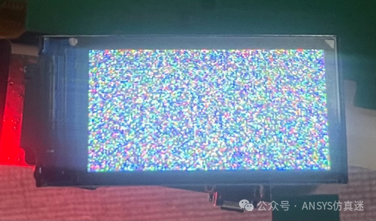 The photo taken by my phone is not very clear, but there is actually a noticeable color deviation because the color bar I want to display is as follows:
const int cb_tbl[8] = { RGB565(255,255,255),RGB565(255,255,0),RGB565(0,255,255),RGB565(0,255,0),RGB565(255,0,255),RGB565(255,0,0),RGB565(0,0,255),RGB565(0,0,0) };This is clearly not matching; the reason is that data is being lost.
void lcd_s_fill(uint16_t x, uint16_t y, uint16_t w, uint16_t h, uint16_t color) { // clipping if((x >= ST7735_WIDTH) || (y >= ST7735_HEIGHT)) return; if((x + w - 1) >= ST7735_WIDTH) w = ST7735_WIDTH - x; if((y + h - 1) >= ST7735_HEIGHT) h = ST7735_HEIGHT - y; LCD_S_CS_LOW; chThdSleepMicroseconds(10); lcd_s_setWindow(x, y, w, h, LCD_RAMWR); uint8_t data[] = { color >> 8, color & 0xFF }; LCD_S_DC_DATA; chThdSleepMicroseconds(10); for(y = h; y > 0; y--) { for(x = w; x > 0; x--) { ST7735_WriteData(data, sizeof(data)); } } LCD_S_CS_HIGH; chThdSleepMicroseconds(10);}So I tried changing to 16-bit data transmission to reduce the number of loop transmissions. Even if there is interference, the number of interference occurrences is halved. However, command operations are all 8 bits, and the default SPI initialization is 8 bits.How can this be achieved? The method is to reinitialize to 16 bits when filling data, and after transmission is complete, reinitialize to 8 bits.
void lcd_s_fill(uint16_t x, uint16_t y, uint16_t w, uint16_t h, uint16_t color) { // clipping if((x >= ST7735_WIDTH) || (y >= ST7735_HEIGHT)) return; if((x + w - 1) >= ST7735_WIDTH) w = ST7735_WIDTH - x; if((y + h - 1) >= ST7735_HEIGHT) h = ST7735_HEIGHT - y; LCD_S_CS_LOW; chThdSleepMicroseconds(10); lcd_s_setWindow(x, y, w, h, LCD_RAMWR); //uint8_t data[] = { color >> 8, color & 0xFF }; spi_init_16bit(); LCD_S_CS_LOW; chThdSleepMicroseconds(10); LCD_S_DC_DATA; chThdSleepMicroseconds(10); for(y = h; y > 0; y--) { for(x = w; x > 0; x--) { ST7735_WriteData16(color); //ST7735_WriteData(data, sizeof(data)); } } spi_init_8bit(); LCD_S_CS_HIGH; chThdSleepMicroseconds(10);}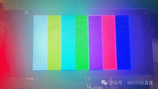 The effect is as shown in the picture, haha, it worked!Finally, I implemented printing text on the LCD, referencing the printf method in nanovna, as shown in the picture.
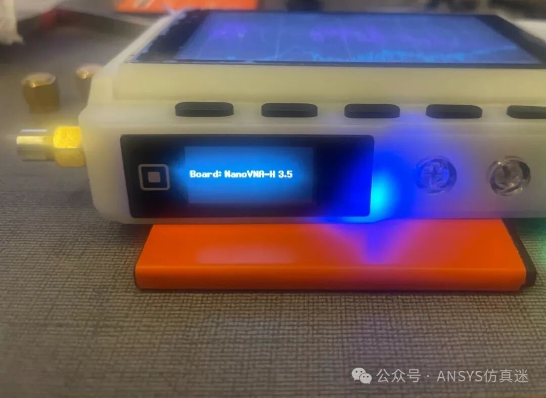 In summary, the two key points are: the need to increase delay; and the 16-bit transmission.END