Light Up an LED
Continuing from the previous discussion, why should we learn to light up an LED before diving into microcontroller programming? The author believes that, first, in this experiment, we can learn how to add functionality to an engineering template; second, we can learn how to configure general-purpose pins to output high and low levels. This chapter is divided into the following sections:
-
Hardware Design
-
Introduction to GPIO Registers
-
Software Implementation
1. Hardware Design
Only one LED is designed on the development board, and the specific circuit is as follows:
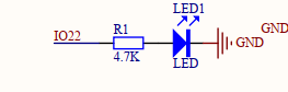
This circuit is simple and easy to understand. The LED is connected to the IO22 pin, and the LED is driven by the pin voltage, meaning it lights up when powered.
2. Introduction to GPIO Registers (Refer to the TMS320F2803x Piccolo Technical Reference Manual for the register manual)
In this section, the author will introduce the registers while configuring the LED pin.
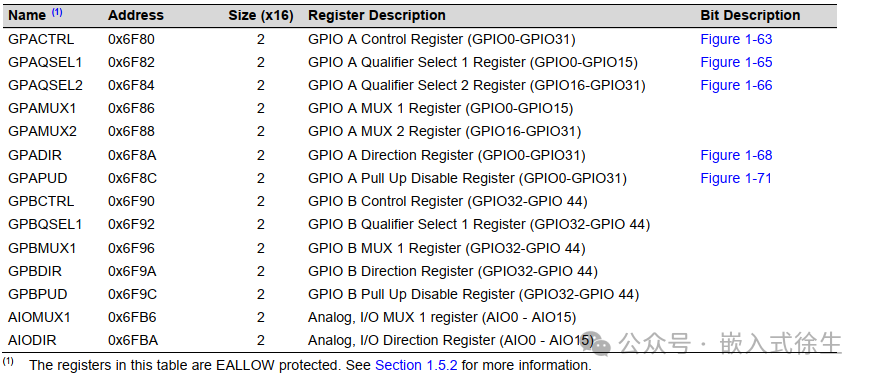
In this example, we are using pin IO22, configured as a general-purpose output mode. From the above register table, we can see that the registers we need to configure include GPACTRL, GPAQSEL2, GPAMUX2, GPADIR, and GPAPUD. (The following registers are summarized based on the author’s understanding; please forgive any inaccuracies and inform the author.)
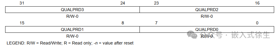
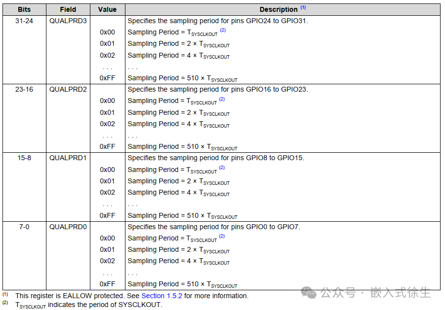
GPACTRL (Port A Control Register)
 Note: Screenshot of the register manual
When the control register is configured to input mode, it sets the sampling window time, where SYSCLKOUT is specified by the GPxQSELn register.
In this experiment, IO22 is configured to output mode, and GPACTRL is set to default 0, meaning this register does not need to be configured.
GPAQSEL2 (A16-A31 Pin Selection Register)
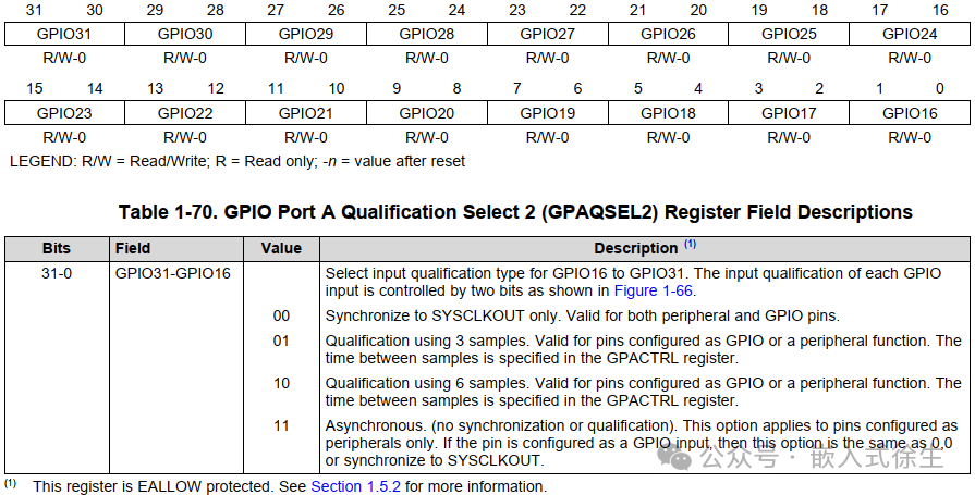
When the pin is configured to input mode, it specifies the sampling period for the pin.
In this experiment, IO22 is in output mode, and the GPAQSEL2 register is set to default 0, meaning this register does not need to be configured.
GPAMUX2 (A16-31 Function Configuration Register)
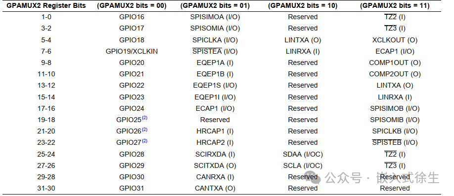
GPAMUX2 sets the function of the corresponding pin:
In this experiment, IO22 is set as a general output, corresponding to bits 13-12 as 00,
i.e., GPAMUX2 = 0x000000;
GpioCtrlRegs.GPAMUX2.bit.GPIO22 = 0;
GPADIR (Port A Pin Input/Output Register)
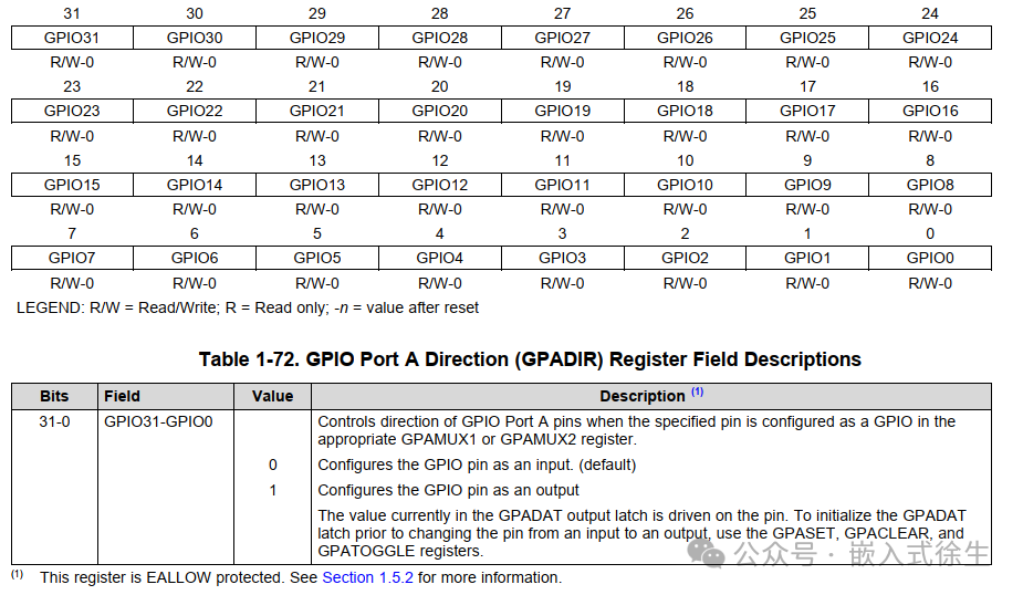
GPADIR configures the input/output register for the pins, the register is 32 bits, with each bit corresponding to a pin, i.e., corresponding to A0-31.0, indicates GPIO input, 1 indicates GPIO output..
In this experiment, IO22 needs to be configured as a general output pin, so:
GPADIR = 0x004000, corresponding to ccs,
GpioCtrlRegs.GPADIR.bit.GPIO22 = 1;
or:
GpioCtrlRegs.GPADIR.all = 0x004000;
GPAPUD (Pin Pull-Up Register)
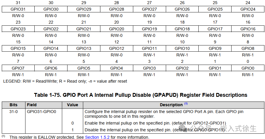
GPAPUD sets whether the pin is pull-up; GPIO12-GPIO31 are by default pull-up, while GPIO0-GPIO11 are by default non-pull-up.
In this experiment, the IO22 pin is set to pull-up, which does not need to be set,
GpioCtrlRegs.GPAPUD.bit.GPIO22 = 0; // Pull-up
This section only briefly introduces the registers for port A and the configuration methods. Although simple, the author’s goal is for readers to understand the configuration methods of the registers, to be able to apply them flexibly, and to boldly configure pins without fear of making mistakes.
3.Software Implementation
From section 2, we know that we only need to configure the pin as output mode, and other registers can be left unconfigured, thus the GPIO pin configuration is as follows:
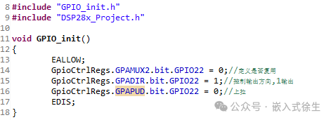
void GPIO_init()
{
EALLOW;
GpioCtrlRegs.GPAMUX2.bit.GPIO22 = 0;// Define whether to multiplex
GpioCtrlRegs.GPADIR.bit.GPIO22 = 1;// Control output direction, 1 for output
GpioCtrlRegs.GPAPUD.bit.GPIO22 = 0;// Pull-up
EDIS;
}
Next, we will implement the LED blinking in the engineering template.
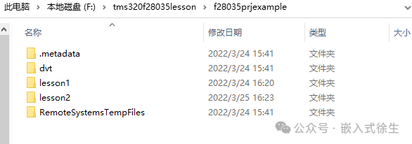
1.Copy the engineering template and rename it to lesson2,(Author’s working path:F:\tms320f28035lesson\f28035prjexample)
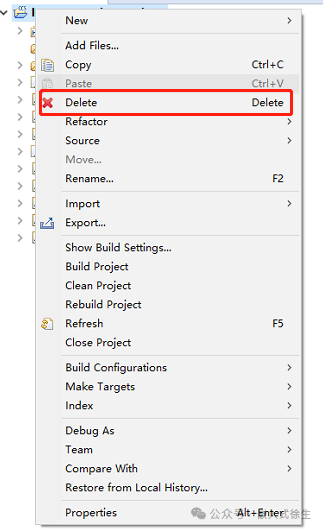
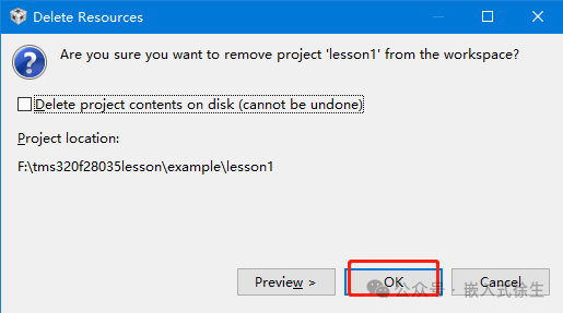
2.Open CCS6, delete the project files in the CCS workspace, otherwise, you cannot import the copied new project.
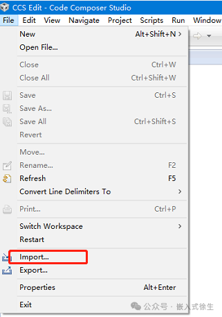
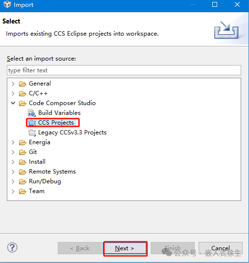
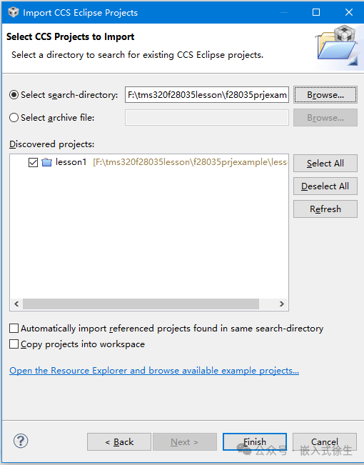
3.Import the project
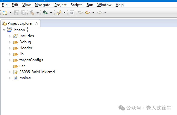
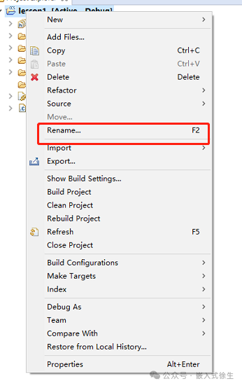
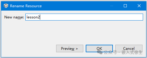
4.Rename the project, right-click on lesson1, select Rename, and rename the project as shown in the figure.
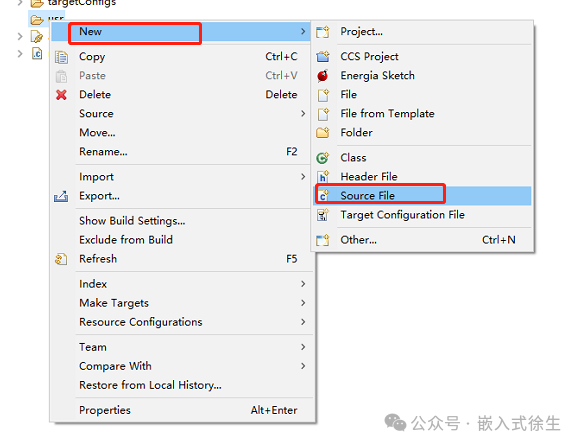
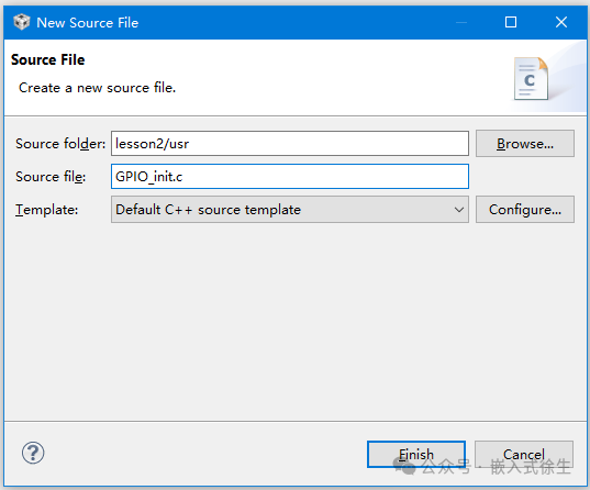
5.Add a new file, right-click on usr -> new -> source file, and enter the name of the file to be added, such as: GPIO_init.c
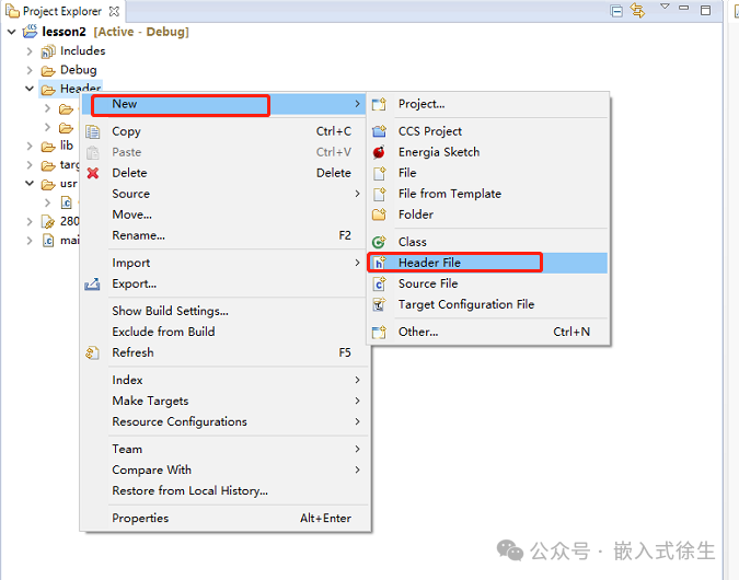
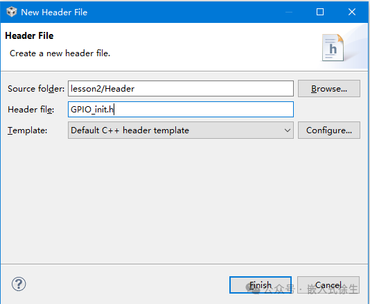
Select Header, right-click -> new -> Header file, and enter the corresponding name of the above c file, such as: GPIO_init.h
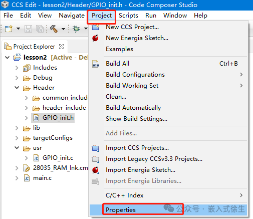
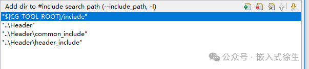
Add the header file, project -> properties,
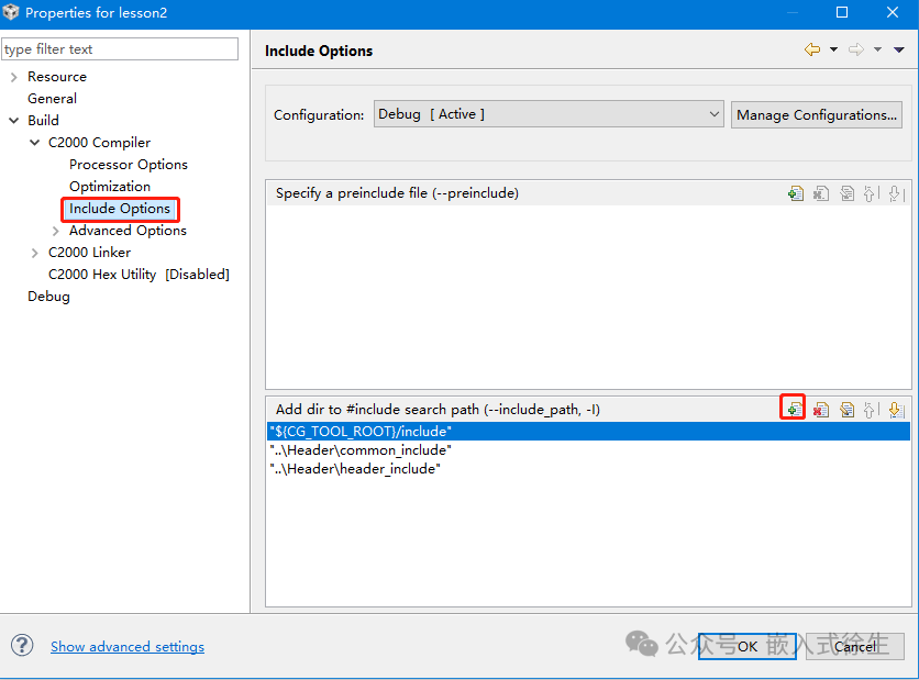
The project will include the header file in the header files.
6.Add initialization code
In GPIO_init.c, add the initialization program
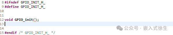
In GPIO_init.h, add
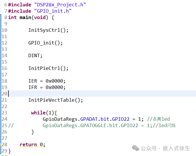
In main.c, add
#include “GPIO_init.h”
Alright, at this point, we have covered how to download the example from the official website, import the example, create a project, and light up the LED. In fact, this also concludes how to use this chip. Some may ask, what about communication, controlling peripherals, etc.? In fact, the principles of each chip are similar; as long as you have used chips from other platforms, you can refer to the example code, reference manual, and register manual here to get started. If you have any questions, please message me, follow me, and reply with dsp28035 to get the materials I collected at that time.