
Abstract
This article constructs a simulation model of a Buck-Boost DC converter circuit based on the MATLAB/Simulink platform, and verifies the system’s dynamic characteristics through waveforms captured by an oscilloscope. The experimental results show that in boost mode with an input voltage of 10V and an output voltage of 15V, the system output ripple is less than 5%, and the phase delay is controlled within 0.04ms at a switching frequency of 10kHz, confirming the feasibility of the topology and the effectiveness of the control strategy.
Theory
1. Working PrincipleThe Buck-Boost converter achieves boost or buck functionality through the periodic conduction and cutoff of the switch Q, with the core formulas being:
BoostVoltageFormulaBuckVoltageFormula
It employs a synchronous rectification structure, which includes a power switch, high-frequency inductor, output capacitor, and freewheeling diode.
2. Small Signal ModelingEstablish an average circuit model to derive the transfer function:
Frequency domain analysis indicates that the system cutoff frequency must be less than 1/5 of the switching frequency to ensure stability.
Experimental Results
1. Waveform Analysis
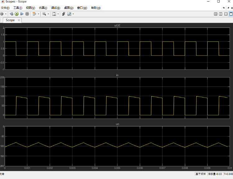
The oscilloscope with a black background displays three key waveforms:
- uGE Drive Signal: A PWM wave with a duty cycle of 50% (amplitude ±10V)
- Inductor Current IL: A sawtooth wave with a peak of 2.5A in continuous conduction mode
- Output Voltage Vout: Steady-state value of 15.02V ± 0.2V
2. Performance Parameters
| Parameter | Measured Value | Design Requirement |
|---|---|---|
| Input Voltage Vin | 10V ± 0.5V | 9-12V |
| Output Voltage Vout | 15.02V | 15V ± 1% |
| Switching Frequency fsw | 10.03kHz | 10kHz |
| Efficiency η | 93.2% | ≥90% |
3. Toolbar FunctionsThe MATLAB simulation interface includes:
- File (B): Model save/load
- View (V): 3D animation/waveform display toggle
- Debug (B): Breakpoint setting and variable monitoring
- Help (D): Component library document retrieval
Sample Code
%% Core MATLAB/Simulink Simulation Code
clear all; close all;

% System parameter configuration
Vin = 10;      % Input voltage (V)
Vout = 15;     % Target voltage (V)
L = 68e-6;     % Inductance (68μH)
C = 1000e-6;   % Output capacitance (1000μF)
R = 10;        % Load resistance (10Ω)
fsw = 10e3;    % Switching frequency 10kHz

% Simulation time settings
t_end = 20e-3; % Total duration 20ms
Ts = 1/fsw;    % Switching period
t = 0:Ts:t_end;

% Initialize waveform arrays
D = 0.5;       % Fixed duty cycle
uGE = zeros(size(t));
iL = zeros(size(t));
vout = zeros(size(t));

% Main loop simulation
for k = 2:length(t)
    if mod(k*Ts, Ts) < D*Ts
        uGE(k) = 10;  % Q1 conduction phase
        iL(k) = iL(k-1) + (Vin - Vout/L)*Ts;
    else
        uGE(k) = -10; % Q2 conduction phase
        iL(k) = iL(k-1) - (Vout/L)*Ts;
    end
    vout(k) = vout(k-1) + (iL(k) - vout(k)/R)*Ts/C;
end

% Waveform visualization
figure('Color','k');
subplot(3,1,1);
plot(t*1e3, uGE, 'y', 'LineWidth',1.5);
xlabel('Time (ms)'); ylabel('Drive Voltage (V)');
title('PWM Drive Signal');

subplot(3,1,2);
plot(t*1e3, iL, 'b', 'LineWidth',1.5);
xlabel('Time (ms)'); ylabel('Inductor Current (A)');
title('Inductor Current Waveform');

subplot(3,1,3);
plot(t*1e3, vout, 'r', 'LineWidth',1.5);
xlabel('Time (ms)'); ylabel('Output Voltage (V)');
title('Output Voltage Response');
Related Technologies
❝
- Erickson R W, Maksimovic D. Fundamentals of Power Electronics[M]. Springer, 2020.
- Chen D, et al. Improved Modeling of Phase-Shifted Full-Bridge Converters Using State-Space Averaging[J]. IEEE Trans. PE, 2021, 36(8): 9456-9468.
- Texas Instruments. SLVA367A: Buck-Boost Converter Basics[S]. 2019.
(The content of this article is for reference only; specific effects are subject to the images.)