1. OTG Interface and Converter
OTG is the abbreviation for “On The Go”, which can be understood as “plug and play”. USB transmission follows a master-slave structure, where all USB transmissions are initiated by the Host.On the development board, a USB flash drive can be inserted, making the development board act as a USB Host.If the development board needs to communicate with a PC, it must act as a USB Device.The development board can serve as both a USB Host and a USB Device, using the OTG port: it can automatically recognize its role based on the hardware circuit and switch between USB Host or USB Device.The OTG port comes in various forms, with Micro USB and Type C being the most common, as shown below: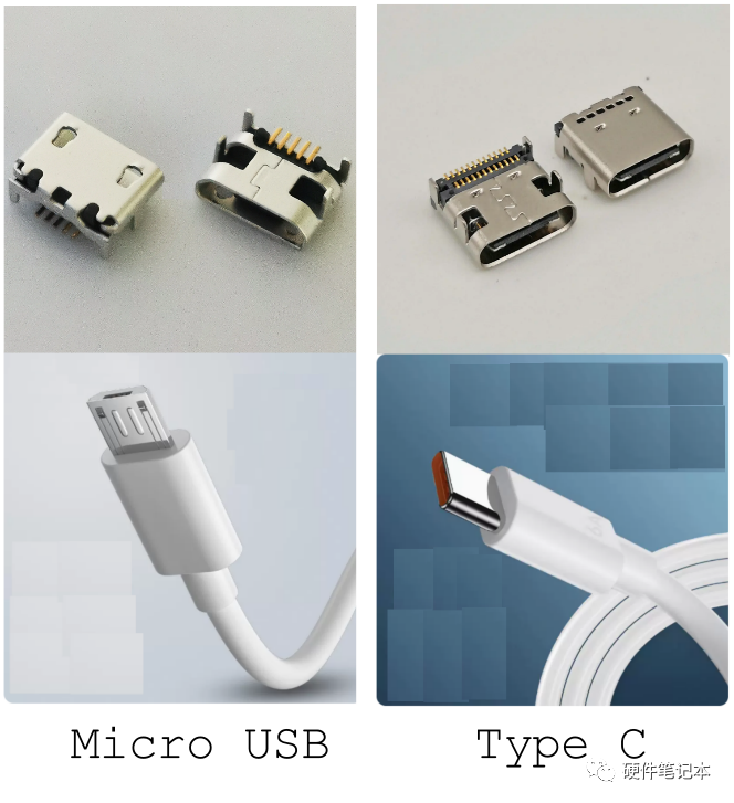
1.1 Micro USB
For the Micro USB socket, it has 5 pins: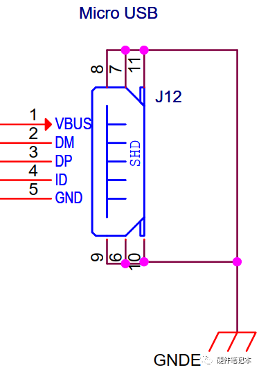 The functions of the pins are shown in the table below:Pin NameFunction
| VBUS | Supplies power when acting as Host; receives external power input when acting as Device |
| DM | Data signal |
| DP | Data signal |
| ID | Pin to determine its role: 1: as Device 0: as Host |
| GND | Ground |
When the development board acts as a USB Device, it connects to the USB on the PC, which only has VBUS, DM, DP, and GND at its USB interface. Therefore, the ID pin of the development board is not connected to the USB port of the PC, as it is pulled high by a pull-up resistor on the board.When the development board acts as a USB Host, it needs to connect to an “OTG converter” before connecting to a USB flash drive. Below is a black converter: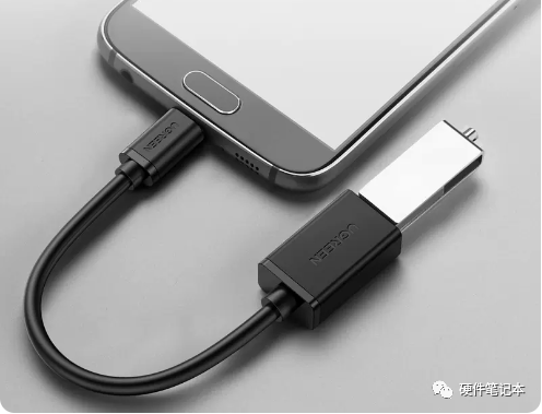 The internal circuit of the OTG converter is simple, which is to pull the ID pin low:
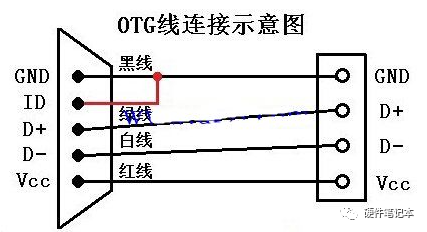 After this converter is plugged into the OTG port of the development board, the ID pin on the OTG port is pulled low, and the software converts the development board into a USB Host.
1.2 Type C
The Type C socket has two sets of identical signals, allowing the Type C data cable to be used regardless of which way it is plugged in: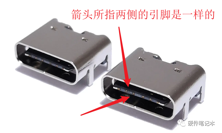 The Type C socket has the following signals, and in the USB2.0 protocol, we only care about the signals in the red box:
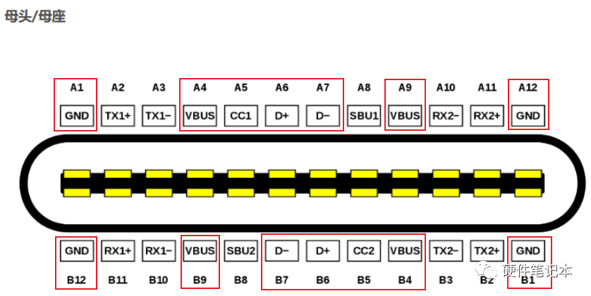 When the development board acts as a USB Device, it connects to the USB on the PC, which only has VBUS, DM, DP, and GND at its USB interface. Therefore, the CC1 and CC2 pins of the development board are not connected to the USB port of the PC, as they are pulled high by a pull-up resistor on the board.When the development board acts as a USB Host, it needs to connect to an “OTG converter”, as shown in the black converter below:
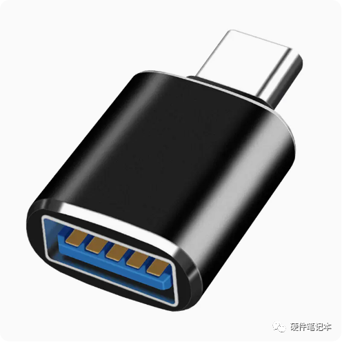 If USB 3.0 protocol compatibility is not considered, the circuit diagram of the above converter is simple: connect the CC pins inside the Type C plug to GND through a 5.1K ohm resistor. As shown in the diagram below: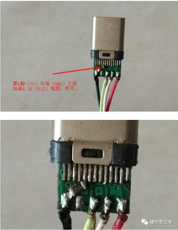
2. OTG Interface Circuit
The OTG interface on the development board needs to achieve two functions:
- Detect the ID pin (for Type C interface, it is the CC1 and CC2 pins), introducing the main control chip: the software sets the USB controller’s role (Host or Device) based on this.
- Decide whether to output power based on the ID pin (or CC1, CC2): the hardware circuit automatically implements this, or a dedicated chip can be added.
2.1 Micro USB
When USB_OTG1_ID is high, it indicates that the ID pin is pulled high by the pull-up resistor on the board and is not pulled low. At this point, AO3416 is conducting, and the EN pin is not enabled. Therefore, SY6280AAAC will not supply power, and USB_OTG1_VBUS will have no voltage.When USB_OTG1_ID is low, it indicates that the ID pin is pulled low, at which point AO3416 is cut off, the EN pin is enabled, SY6280AAAC supplies power, and USB_OTG1_VBUS has voltage, making the development board act as a USB Host supplying power.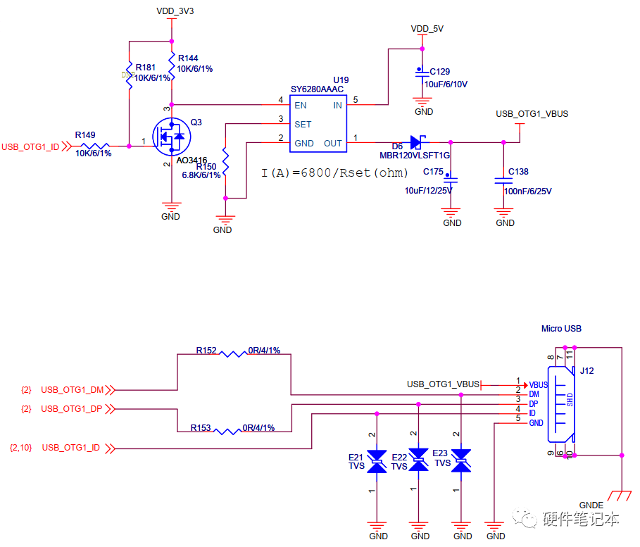
2.2 Type C
If USB 3.0 protocol compatibility is not considered, the following simplified circuit can be used: CC1 and CC2 serve as the ID pins. The principle is similar to the above diagram.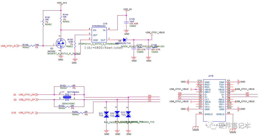 If USB 3.0 protocol compatibility is required, a dedicated chip needs to be added. The dedicated chip detects the state of CC1 and CC2, sends an interrupt to the main control, and reports the information to the main control via I2C, which then controls the power supply pin: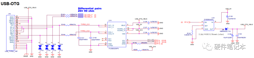
References:
Wei Dongshan’s Complete Guide to Drivers
https://www.lulian.cn/news/otg_gongneng_jiexi-cn.html
https://www.elecfans.com/connector/20180309645002_a.html
https://blog.csdn.net/qq_37659014/article/details/124479125
Article reprinted from: Embedded Linux System Development, please delete if infringed.


 Click to read the original text, apply for free