1. Introduction
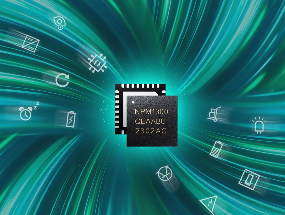
Recently, I received a board sent by Breadboard Community, which is based on the evaluation kit of Nordic’s latest nPM1300 power management chip. Regarding power management chips, many are familiar with discrete chips, such as buck-boost converters, power monitoring, POR resets, and charge-discharge management functions, but it is rare to find all these functions integrated into a single chip. In this article, we will experience the world’s first integrated power management IC (PMIC) that includes all necessary functions — nPM1300.

Breadboard Community is currently applying for nPM1300
Students in need can scan the code to apply for free
2. Nordic Semiconductor
nPM1300 is a PMIC power management chip from Nordic. Nordic, established in 1983, is well-known among friends developing Bluetooth low-power products. It is the pioneer of ultra-low-power wireless technology and a representative enterprise in the wireless technology field. Nordic is headquartered in Norway and has technologies such as Bluetooth, ANT+, Thread, Zigbee, WiFi, and NB-IoT.Nordic’s low-power Bluetooth SoCs are widely used in the IoT field due to their high performance and ease of design, including wireless PC peripherals, gaming, sports and fitness, mobile accessories, consumer electronics, toys, healthcare, and automation products.Although many SoCs have integrated power management functions, due to limitations in power consumption, efficiency, and charge-discharge management, many users still require external power management chips to meet complex functional needs. Common power management chip architectures are usually quite simple, generally supporting multiple adjustable voltage outputs and external battery charge-discharge management.
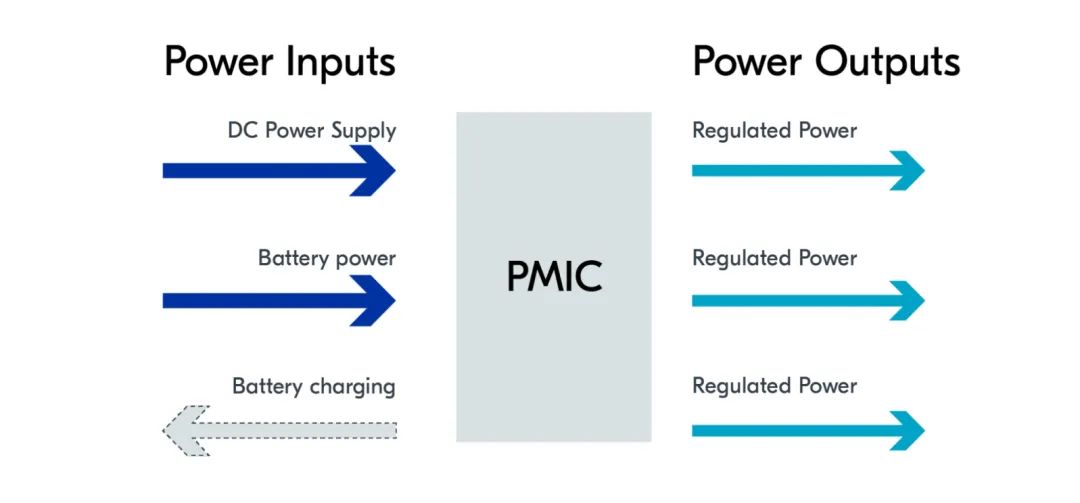
With the demands of smart homes and wearable products for product size, performance, and battery life, the functions of power management chips have also increased, such as:
- Hardware reset required in abnormal situations
- Longer battery life
- Accurate battery level statistics
- Fast and safe charge-discharge
- Smaller size and higher efficiency
The power management IC we are evaluating in this article — nPM1300 includes all the above functions.
3. nPM1300 Evaluation Kit Hardware Resources
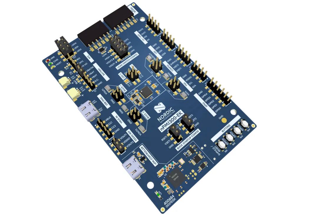
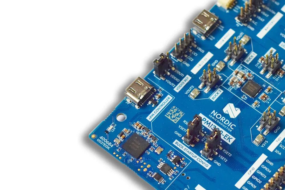
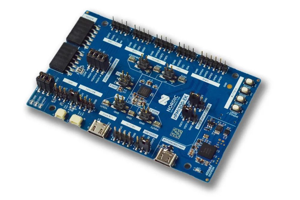
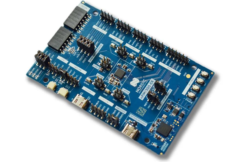
Like many of Nordic’s development boards and evaluation boards, the nPM1300 evaluation kit also adopts a blue-green PCB design. The overall dimensions of the board are 100mm long and 64mm wide, using a 4-layer PCB design based on Altium Designer design software.
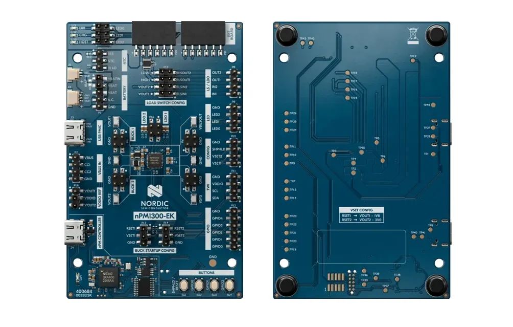
All hardware documentation is provided by the official, including PCB and schematics, drilling files, BOM, Gerber, and all files needed for production design and manufacturing. Let’s take a detailed look at the hardware resources of the board:
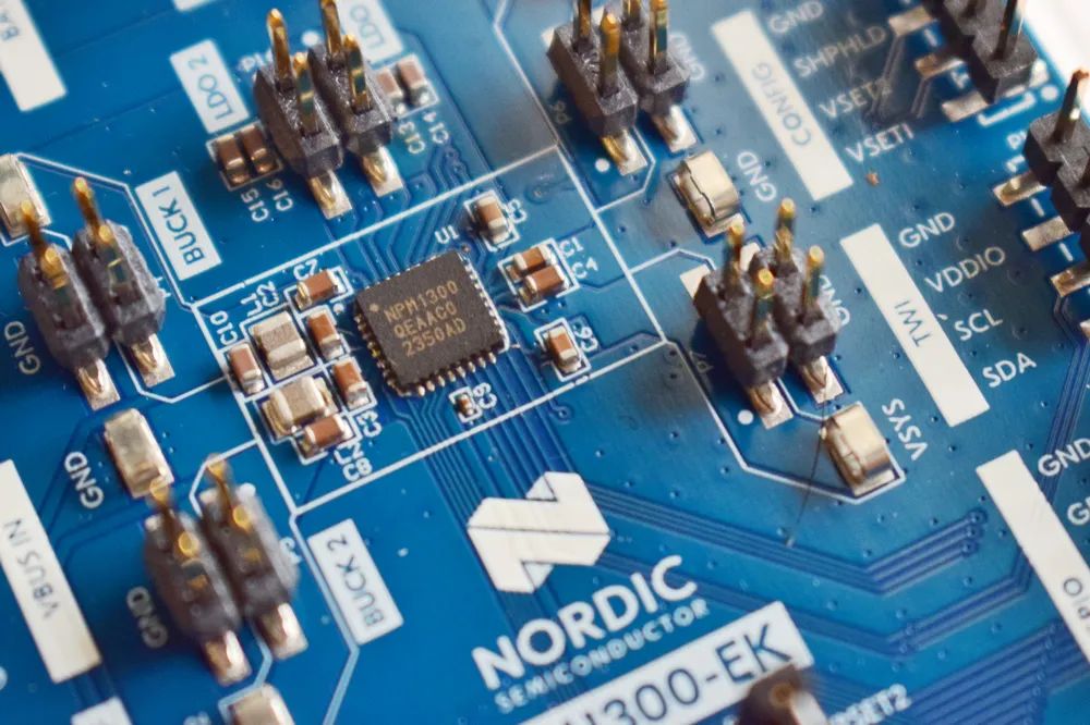
- nPM1300 core chip, QFN32 package, all pins are led out through standard 2.54mm pitch pin headers for flexible evaluation and measurement
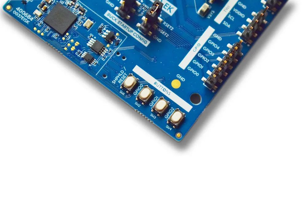
- 1 SHPHLD button, 3 GPIO tactile buttons, 3 LED indicators
- Supports two battery interfaces, with and without NTC batteries
- The main control chip is nRF5340, connected to the host computer via USB serial port, and configures the nPM1300 registers via IIC communication
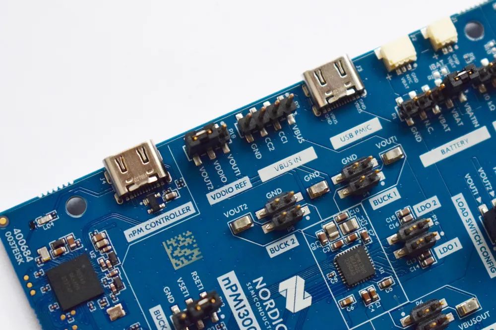
- Two USB-C interfaces, one connects to nRF5340 for USB serial port functionality, the other directly connects to nPM1300
- Multiple voltage test points for easy connection with oscilloscopes or multimeters
- A set of external expansion interfaces for connecting compatible power meter expansion boards
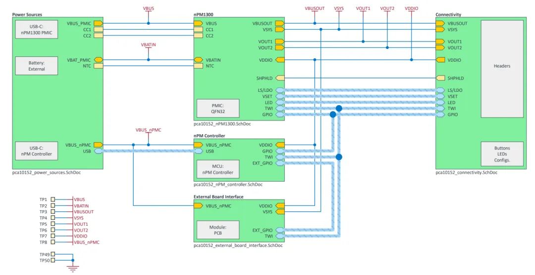
The system block diagram of the nPM1300 evaluation kit is as follows:
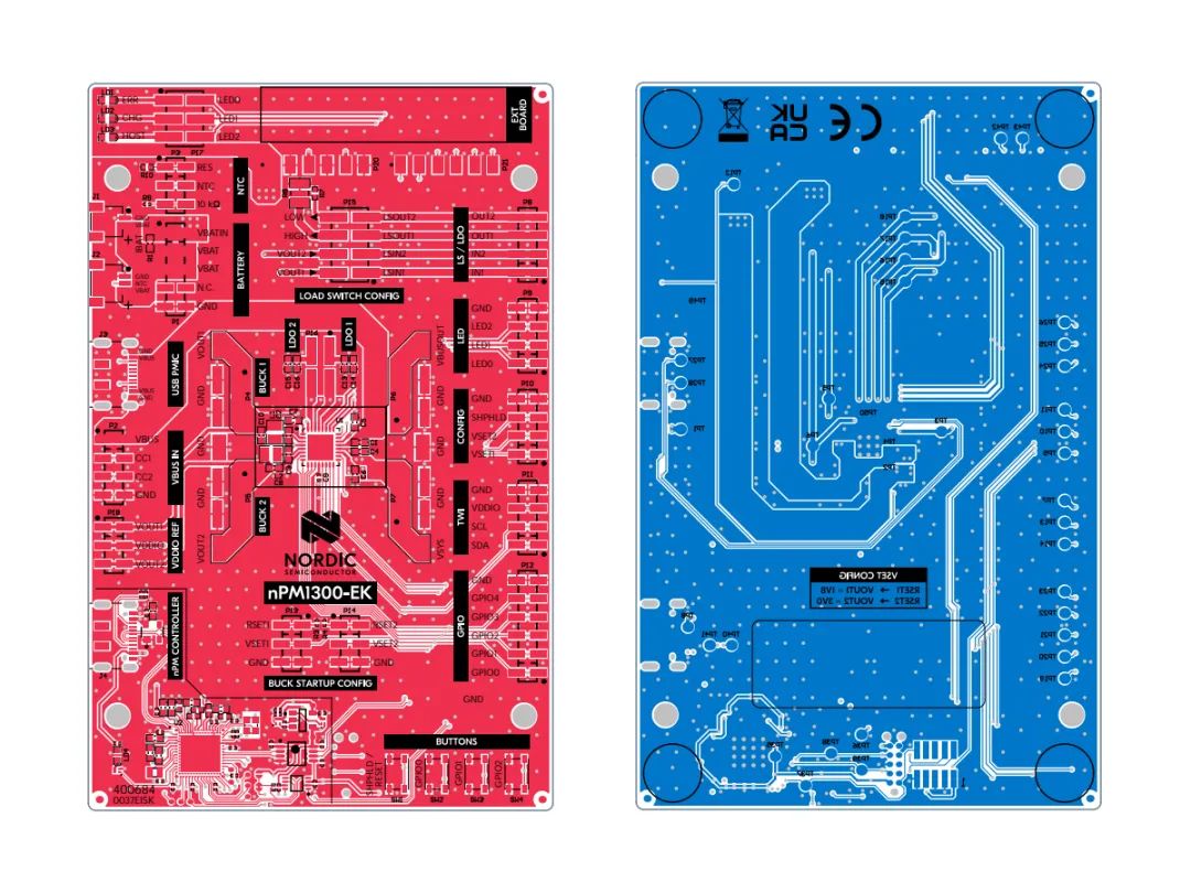
Top and bottom layers of the PCB
3D effect of the PCB:
Close-up of the nPM1300 chip
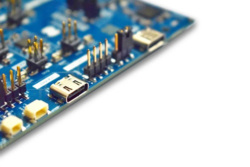
USB-C interface
Onboard 3 user buttons
LED
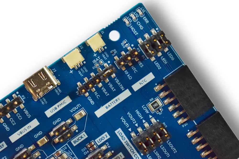
Battery interface
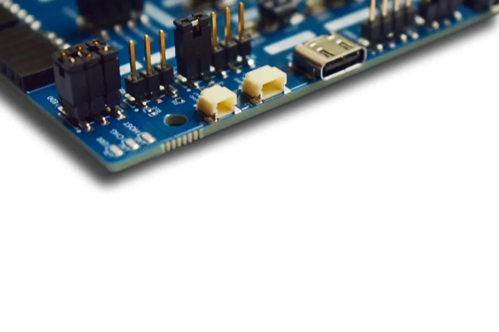
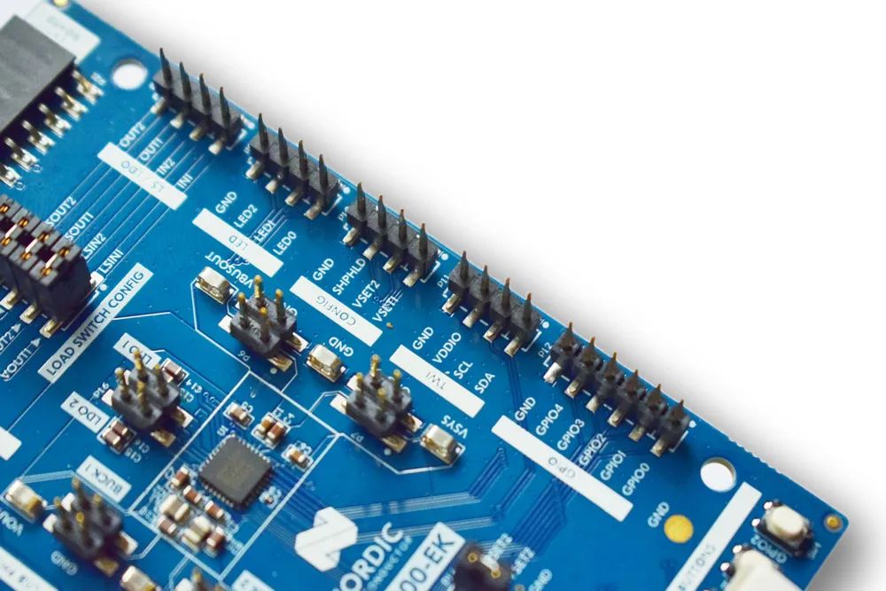
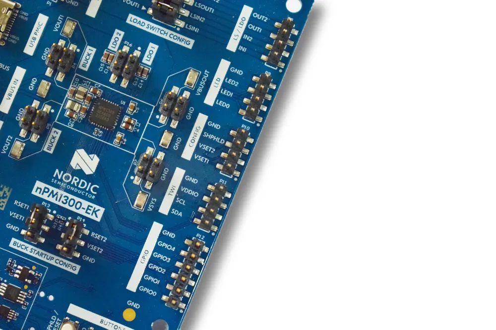
Pins led out through pin headers
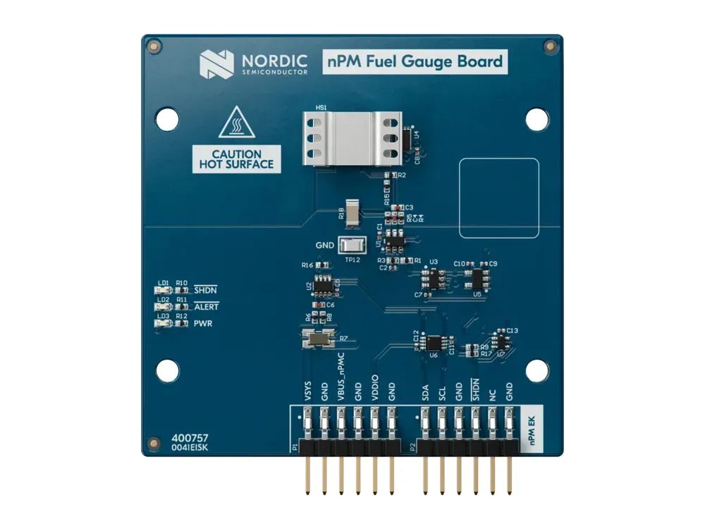
The expansion interface can connect to the power meter expansion board shown in the figure below, used to generate the battery’s charge-discharge model.
4. Introduction to nPM1300 Chip Features
After understanding the hardware resources of the evaluation board, let’s focus on the core of the board — nPM1300 chip.From the official datasheet, we can see the internal structure of the chip:
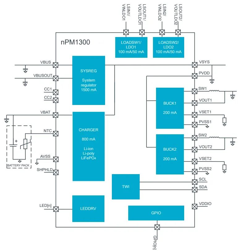
It mainly includes the following parts:
- DC-DC BUCK converter
- Battery charge-discharge management
- GPIO and LED driving part
- Digital interface bus part
- Load switch part
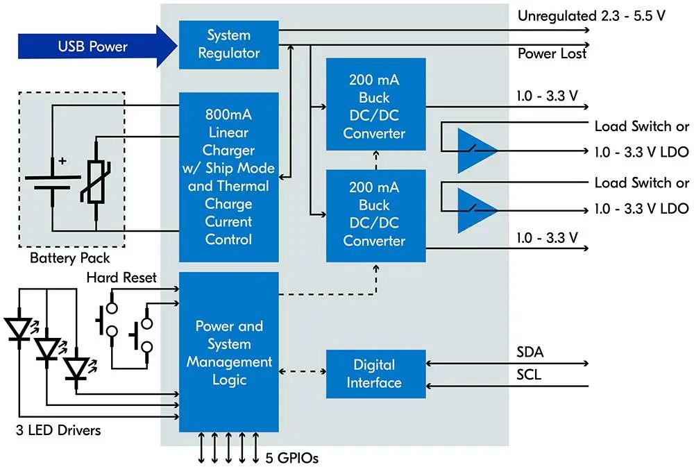
The detailed electrical characteristics of the nPM1300 are as follows:
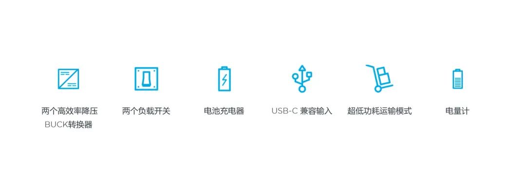
- Two ultra-efficient DC-DC buck outputs, adjustable from 1.0-3.3V, with a maximum output of 200mA
- Charging current adjustable from 32-800mA, with a step of 2mA, supporting NTC input, output voltage from 3.5V to 4.45V
- No limit on battery capacity, supports lithium-ion batteries, lithium polymer batteries, and lithium iron phosphate batteries
- Two 100mA load switches or 50mA LDO, supporting voltage from 1.0-3.3V
- Supports USB Type-C interface, with CC pins directly connected to the chip pins, the chip has a built-in 5.1k pull-down resistor, no external configuration needed
- Input voltage from 4.0-5.5V, with a maximum of 1.5A and 22V over-voltage protection
- 5 configurable GPIOs and 3 configurable LED outputs
- Fully compatible with I2C TWI digital bus interface, supporting speeds up to 400KHz
- Manufactured using 180nm process, operating temperature range from -40℃ to 85℃, with PN junction temperature below 125℃
- Two hardware resets, watchdog timer, wake-up timer, general timer
- 10-bit precision ADC for measuring input voltage, battery voltage, current, and chip temperature
- Supports power statistics function, sampling battery voltage, current, temperature values through the internal ADC, and can accurately perform power statistics through official algorithms
- Over-voltage, under-voltage, over-current protection, temperature protection
- Ultra-small packaging size: 3.1×2.4 mm WLCSP and 5.0×5.0 mm QFN
- Requires at least 5 passive components to use
- Supports ultra-low power transport mode, with static current of 370nA in factory mode
- Graphical interface configuration, one-click export configuration to the user’s MCU application
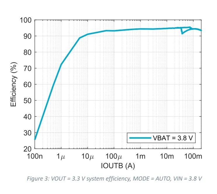
The conversion efficiency under different output currents can reach up to about 95%, which is very efficient!
Common application scenarios include:
- Wearable devices
- Handheld entertainment devices
- Portable medical devices
- Rechargeable smart home sensors
- Mice, keyboards, touchpads
- Body-sensing games and other interactive entertainment devices
- Low-power sensors and other IoT devices
5. nPM1300: One is Better than Eight
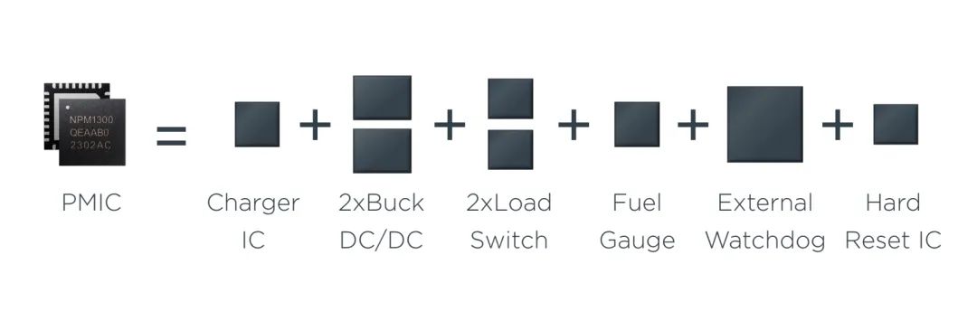
nPM1300 can make users’ work easier, hardware engineers do not need to write code, and software engineers do not need to read datasheets. It is ready to use right out of the box; you only need to set it up in the intuitive graphical user interface (GUI) and export the overlay file, then add it to your SDK project for use.Compared to multiple independent power management chips, nPM1300 integrates almost all the functions of power management chips, combining the functions of the following 8 chips:
- 1 charging management chip
- 2 BUCK buck chips
- 2 load switch chips
- 1 power meter chip
- 1 watchdog chip
- 1 hardware reset chip
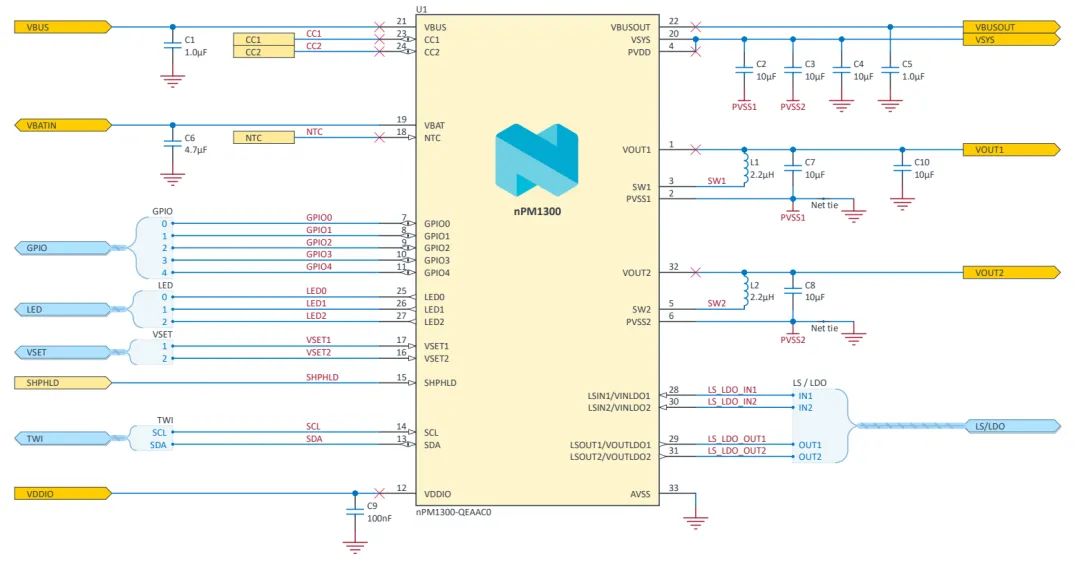
Conventional discrete chip designs require many passive components, leading to complex schematics, large PCB area, and high BOM costs. The nPM1300 requires very simple peripheral circuitry, needing only 5 passive components to use.
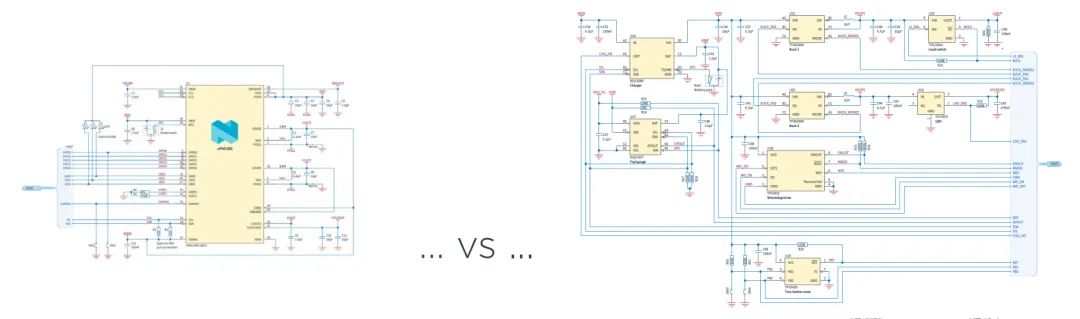
The official provides two recommended layout schemes for packaging:https://nsscprodmedia.blob.core.windows.net/prod/software-and-other-downloads/reference-layouts/npm1300/qfn/npm1300-qeaa-reference-layout-1_1.ziphttps://nsscprodmedia.blob.core.windows.net/prod/software-and-other-downloads/reference-layouts/npm1300/wlcsp/npm1300-caaa-reference-layout-1_0.zipComparison of conventional discrete chip schematic design with nPM1300:
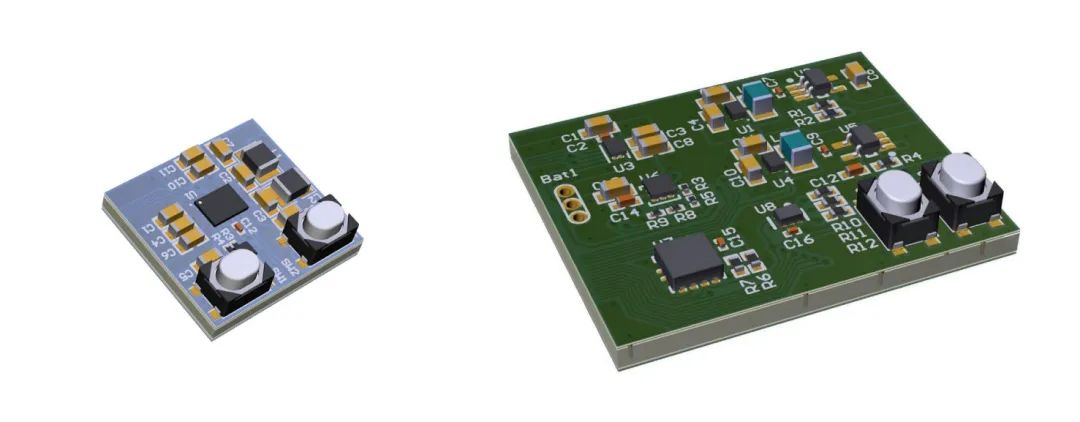
PCB size comparison design:
It can be said that nPM1300 is truly one is better than eight!
6. User Experience of nPM1300 Evaluation Kit
Next, let’s briefly use the nPM1300 evaluation kit. Since I do not have a usable lithium battery on hand, this experience will not involve charge-discharge, power meter, and other functions.First, you need to download the supporting host computer software: nRF-Connect-for-Desktop, which supports the three major platforms: Windows, Linux, and MacOS. The latest version is:nrfconnect-setup-4.4.1-x64.exe. After downloading, install it; it will also install the Jlink driver:
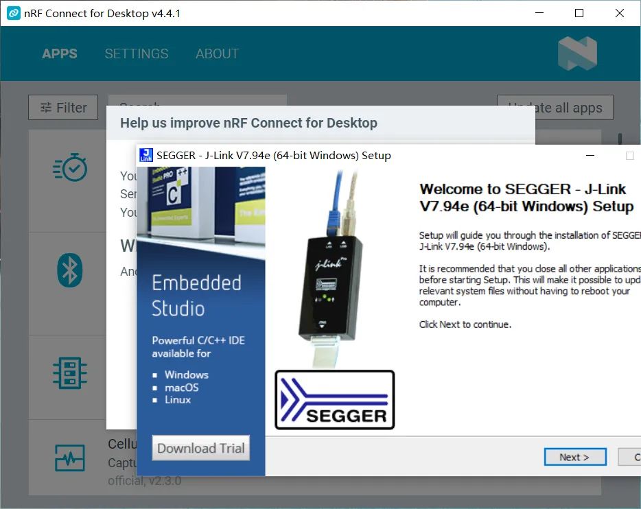
After installation, open the software, and you will see that this tool is a collection of commonly used host software for Nordic chips. Since we are evaluating PMIC, we also need to install nPM PowerUP.
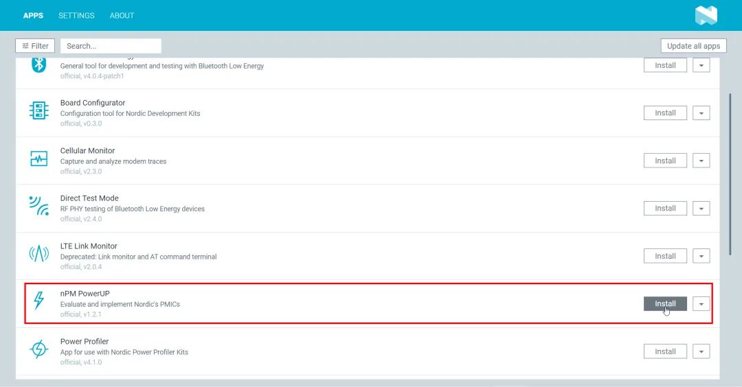
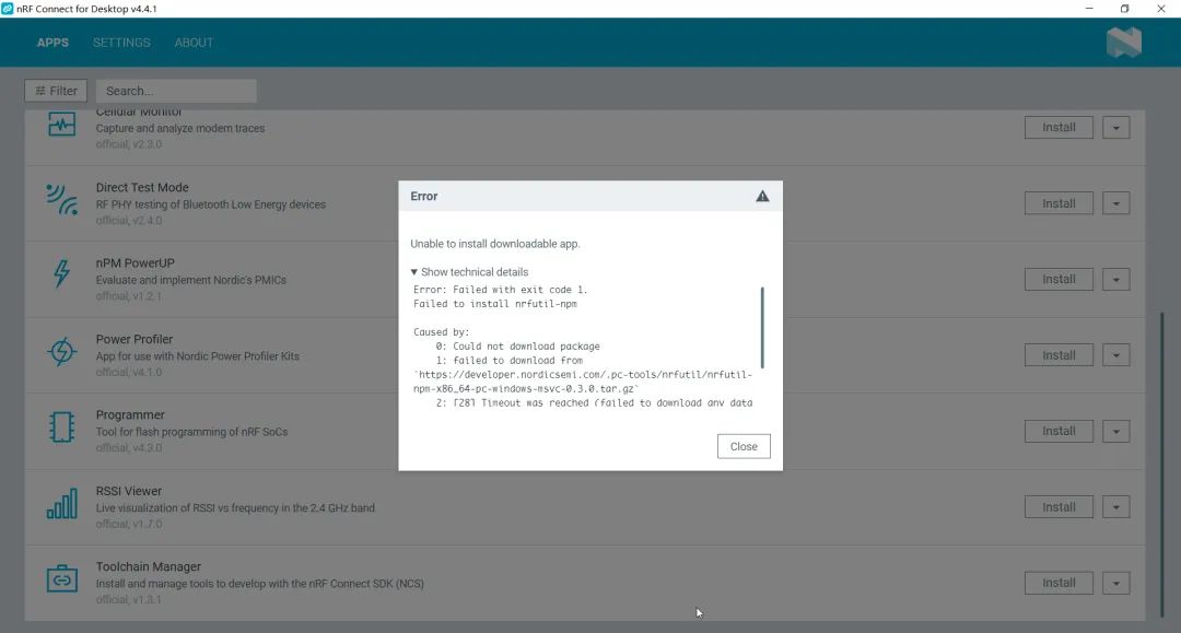
If installation fails, you can try a few more times or restart the computer.
After installation, prepare two Type-C USB data cables, and connect the two USB interfaces of the board to the computer. You will see the LD4 indicator light breathing. If the USB PMIC interface is not connected, the LD4 indicator light will be in a fast flashing state.
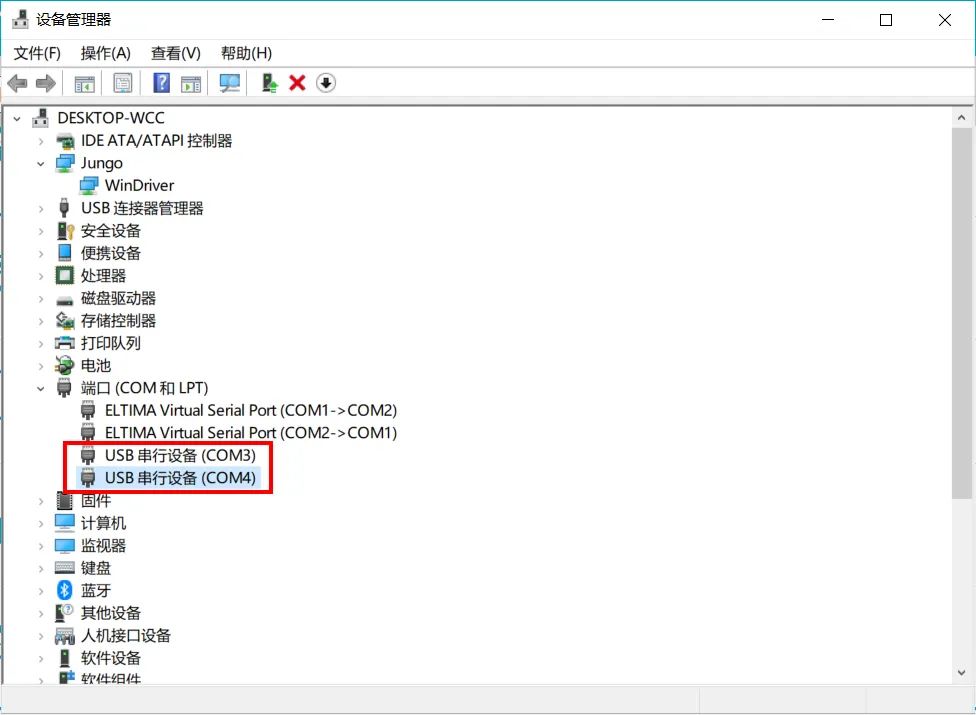
After connecting to the computer, the device manager will show two additional serial numbers:
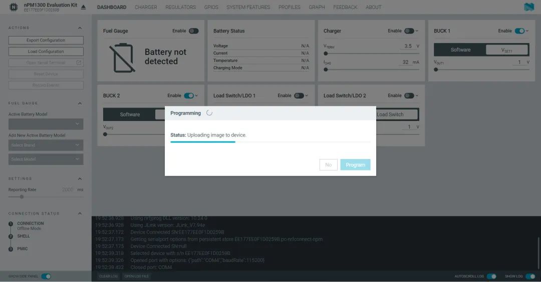
On the first use of this software, you need to update the firmware of the SoC on the board:
Open the nPM PowerUP software to connect the board, and you can see the logs in the bottom console:
14:52:40.188    Device Connected SN:EE177EE0F1D0259B
14:52:40.189    Getting serialport options from persistent store EE177EE0F1D0259B.pc-nrfconnect-npm
14:52:40.190    Device Connected SN:null
14:53:45.467    Selected device with s/n EE177EE0F1D0259B
14:53:45.478    Opened port with options: {"path":"COM4","baudRate":115200}
14:53:45.575    Closed port: COM4
14:53:45.575    Device setup ready for device with s/n EE177EE0F1D0259B
14:53:45.581    Opened port with options: {"path":"COM4","baudRate":115200}
14:53:47.831    Reset cause: SWRESET
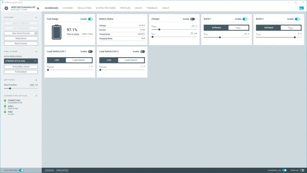
The graphical interface is shown in the figure below:
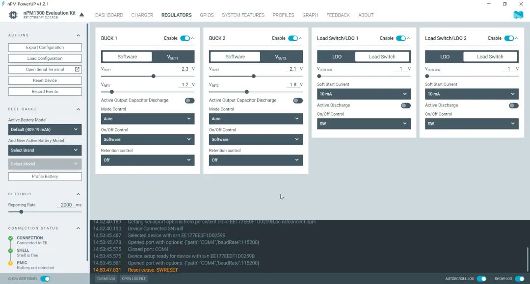
The basic functions of each window:
- DASHBOARD: Overall configuration of nPM1300 chip
- CHARGER: Battery charging current and voltage configuration
- REGULATORS: DC-DC converter and load switch configuration
- GPIOS: Configuration of 5 GPIOs and 3 GPIOs
- SYSTEM FEATURES: Configuration of system reset, timers, POR, input current, etc.
- PROFILES: Creating and loading battery models
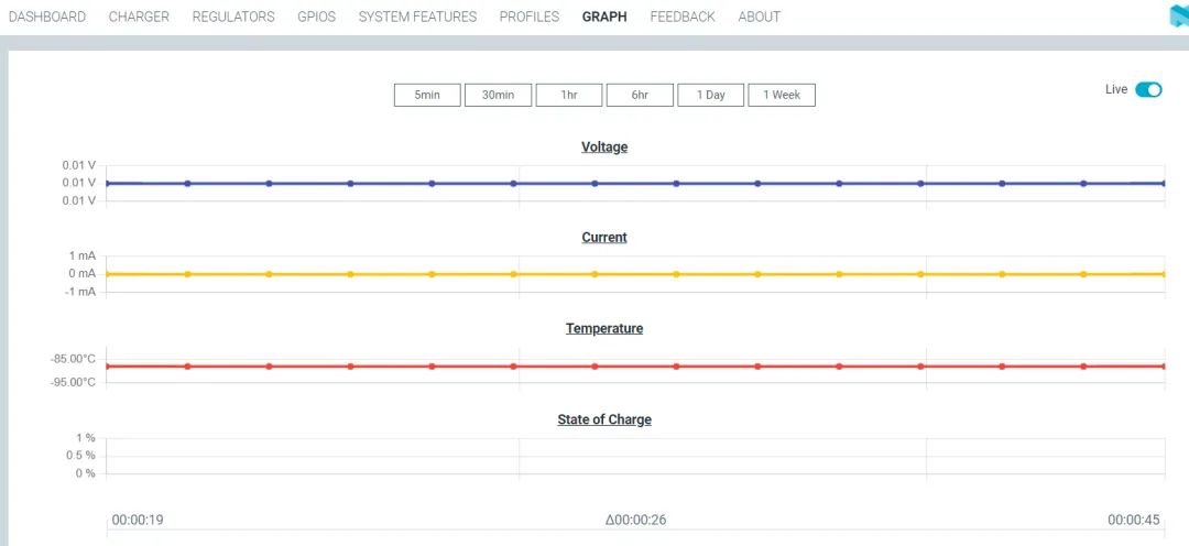
- GRAPH: Real-time curves of battery voltage, current, and temperature
You can adjust the output voltage value using the slider or by manually entering numbers, and measuring the voltage values of VOUT1 and VOUT2 with a multimeter or oscilloscope will show changes with the set values. Since I do not have a usable lithium battery on hand, this evaluation did not assess charge-discharge and power statistics functions.
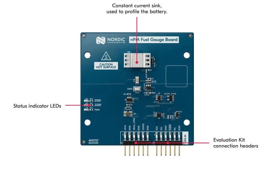
Interested friends can connect a battery for testing, and you can see real-time battery voltage, current, temperature, and other information in the software.
The official also provides a power meter expansion board compatible with this evaluation kit — nPM Fuel Gauge Board, which generates the charge-discharge model data for the battery. According to the official introduction, within 12 hours under temperature changes from -20°C to +60°C, the software algorithm’s power meter accuracy error is within 3%.
After configuring the chip, click on the left <span>Export Configuration</span>, export the current configuration, and you can choose <span>overlay</span> and <span>json</span> file formats. The overlay file can be used in our MCU applications; after adding this file to the project, it will be called in the Zephyr TWI driver.
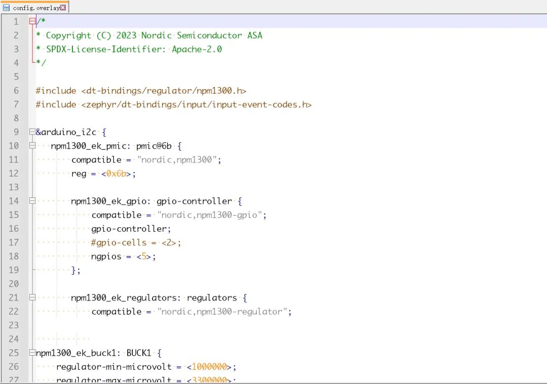
To execute the device tree overlay file, please click on “edit build configuration” in the nRF Connect for VS Code extension, and then use the “Add overlay” button under “Devicetree overlay” to add the overlay file.
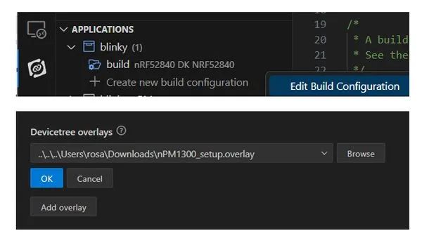
Make sure the <span>prj.conf</span> includes these configurations:
CONFIG_GPIO=y
CONFIG_SHELL=y
CONFIG_LOG=y
CONFIG_REGULATOR=y
CONFIG_SENSOR=y
CONFIG_LED=y
If your application does not enable the IIC bus, you also need to add the following lines of code at the end of the file:
&i2c0_default {
  group2 {
    psels = <NRF_PSEL(TWIM_SCL, 0, 27)>, <NRF_PSEL(TWIM_SDA, 0, 26)>;
    bias-pull-up;
    };
  };
/delete-node/ &{/pin-controller/i2c0_default/group1/};
This will enable the internal pull-up for the I2C lines, where 27 and 26 specify the SDA and SCL pin numbers of the used SoC.
7. Supporting Materials for nPM1300 Evaluation Kit
The supporting materials for the evaluation kit are very comprehensive, making it almost ready for developers to use, mainly including:
- Board hardware documentation package, including schematics, PCB, BOM, Gerber filesnsscprodmedia.blob.core.windows.net/prod/software-and-other-downloads/dev-kits/npm1300-ek/npm1300-evaluation-kit—hardware-files-1_1_0.zip
- Chip datasheetinfocenter.nordicsemi.com/pdf/nPM1300_PS_v1.0.pdf
- Introduction to nPM1300 EK evaluation kitwww.nordicsemi.com/-/media/Software-and-other-downloads/Product-Briefs/Translated-versions/nPM1300EK.pdf
- nPM1300 chip product introductionwww.nordicsemi.com/-/media/Software-and-other-downloads/Product-Briefs/Translated-versions/nPM1300-PMIC_PB_SC.pdf
- Visual graphical configuration softwarewww.nordicsemi.com/Products/Development-tools/nrf-connect-for-desktop
8. References
- nPM1300 official homepagewww.nordicsemi.cn/products/npm1300/
- nPM1300 EK official homepagewww.nordicsemi.cn/tools/npm1300ek
- nPM1300 hardware design guidehttps://infocenter.nordicsemi.com/topic/nwp_050/WP/nwp_050/intro.html?cp=7_1_4_1
- In-depth analysis of Nordic’s new generation PMIC application in low-power wireless IoT devices (Part 1)www.eeyxs.com/livebroadcast/index/playback.html?tid=842&cid=6471
- In-depth analysis of Nordic’s new generation PMIC application in low-power wireless IoT devices (Part 2)www.eeyxs.com/livebroadcast/index/playback.html?tid=842&cid=6472
- nPM1300 and nRF54 series solutionswww.eeyxs.com/livebroadcast/index/playback.html?tid=842&cid=6473
- Webinar on July 5, 2023, by Nordic’s power management product director Geir Kjosavikwww.youtube.com/watch?v=aN5umN5zV0E
9. Conclusion
This article introduces the features of the nPM1300 power management chip and briefly experiences the basic functions of the evaluation kit and the basic usage of the graphical configuration interface. During the process, it can be found that this chip is very easy to use, almost without needing to read the datasheet or write code to apply it in the project. It should be noted that the nPM1300 cannot be used independently; it requires an MCU host for configuration and control through the I2C interface. The official recommended typical application is to use it with the nRF52 and nRF53 series SoCs, but it can also be used with other non-Nordic chips.
Overall, the high integration of nPM1300 significantly reduces users’ workload, and its ultra-low power consumption and ultra-high efficiency are the advantages of this chip, making it very suitable for low-power IoT devices that do not require high current.
Author: wcc149
Source: Electronic Circuit Development Learning
END Apply for Free
👆 Scan the QR code above to apply for the nPM1300 power management IC for free 👆
The nPM1300 evaluation kit (EK) can perform simple evaluations of the nPM1300 power management IC (PMIC) and no-code configuration. By connecting the nPM PowerUP application in nRF Connect for Desktop, all settings of nPM1300 can be easily configured through an intuitive GUI and exported as code for implementation in the MCU application.
This kit itself has a JST battery connector for batteries with or without internal NTC, and public pin headers for connecting all nPM1300 connections. Additionally, this kit comes with three LEDs and four buttons to easily evaluate the GPIO and LED drivers of the PMIC device.