
This article is a highlight from the KX forum, authored by KX forum user ID: Lpwn
1
Overview
Using an old project on fan control as an experiment.

It utilized external interrupts, timer interrupts, and PWM. The MCU is STM32F103ZET6.
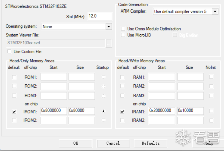
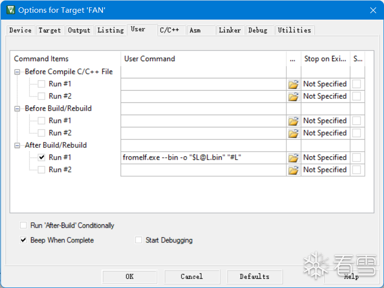
In the Keil settings, you can see the starting address of the firmware, which is 0x8000000 by default. Additionally, Keil generates a hex file, which is a bin file with base address information. To generate a bin file, the following settings are required:
Moreover, the firmware programmed into the MCU does not contain symbol tables or debugging information, meaning both hex and bin files lack debugging information due to the limited memory of the MCU. However, Keil will generate a separate axf file with debugging information, which we can use as a reference to recover the bin or hex files. Below, we will observe the differences between these three files:
First, the axf file

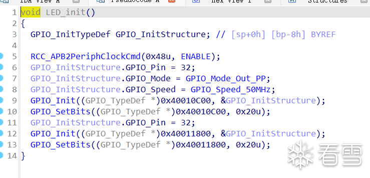 It is almost identical to the source code, except for some peripheral names replaced with addresses.
Next, the hex file:

First, change the architecture to ARM little-endian, and then modify the architecture version; STM32F103ZET6 uses the Cortex-M3 core, ARMv7 architecture.

After making changes, load the hex file.

IDA will automatically recognize the base address and can identify many functions, but the pseudocode is quite unreadable.
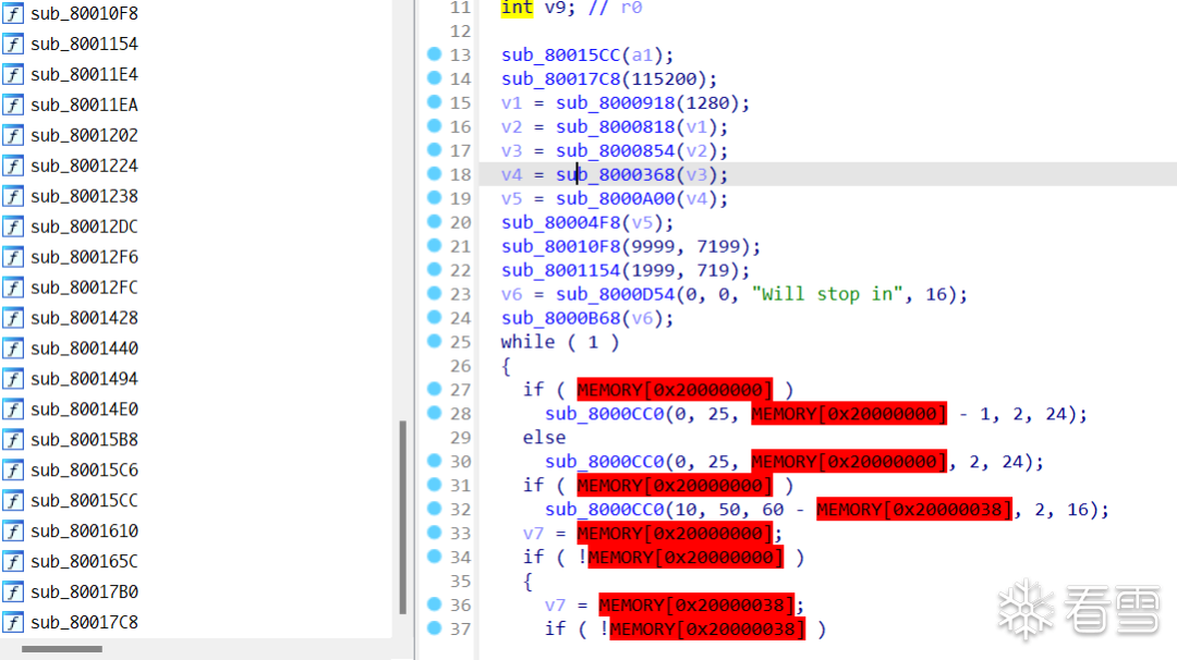
It’s basically unreadable.
Finally, the bin file.

The bin file is a hex file without address information, requiring manual base address settings.
2
Manually Set Firmware Base Address
Our analysis will target the bin file.
Reset the base address to 0x8000000. Where does this address come from? You can check the STM32F103ZET6 datasheet.
From 0x8000000, it is the flash space.
After resetting the loading address and parsing the code, it will become the appearance of the hex file.

However, at this point, there are many red-highlighted addresses because these addresses have not been set in IDA, so IDA interprets them as illegal addresses and highlights them in red. What we need to do now is manually add some segments.
3
Add SRAM
Segments are in the axf file, and IDA has parsed the following segments:
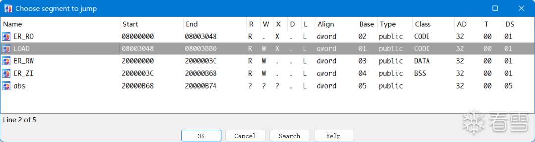
Microcontroller memory is generally divided into flash (ROM) and SRAM (RAM). Data in flash can be retained after power loss, while data in SRAM is lost. SRAM execution speed is faster than flash, and flash capacity is larger than the minimum memory address in SRAM, with the highest address also being in flash and SRAM.
When we download programs, they are typically stored in flash, which is why they can be retained after power loss.
Microcontroller program storage is divided into code (code storage area), RO-data (read-only data storage area), RW-data (read-write data storage area), and ZI-data (zero-initialized data area). Flash stores code and RO-data, while SRAM stores RW-data and ZI-data.
In the datasheet, you can also find the starting address of SRAM, which is 0x20000000, and the ending address is 0x2000FFFF. When adding segments, we don’t need to be as detailed as IDA’s automatic analysis; a single SRAM segment will suffice.
You can also set the firmware loading address and the start and end addresses of SRAM when starting IDA. After adding the SRAM segment, the red illegal addresses will disappear, as shown below:

4
Restore Symbol Table
Next, we need to restore the symbol table. Since the bin file lacks debugging information, the pseudocode generated by IDA is almost unreadable. To facilitate our reverse engineering, we need to restore function names and import some structures. Here, we will use the axf file.
Earlier, we saw that the axf file is almost identical to the source code and contains rich debugging information. Of course, we won’t use this course project axf file to restore the bin file, as that would be too deliberate.
Since my course project used library functions for development, I cannot use the HAL library generated by STM32Cube for recovery. How to restore? We will use bindiff to restore the symbol table.
If you have spare time or are very familiar with STM32 development, you can write a demo yourself, trying to use as many library functions as possible, and then compile an axf file. In my case, since I haven’t used STM32 for a long time and am a bit rusty, I chose to pick an existing project. When I learned STM32, I bought a development board from XX Atomic, and they provided a wealth of examples, over fifty, ranging from easy to difficult, covering all aspects of STM32 development. Therefore, I directly took a part of these examples to compile an axf file. For instance, the following memory allocation example:
Also, this PWM example:
You can select several examples to cover more library functions, open these axf files in IDA, and then generate idb files. Then, in our target bin file, use bindiff to load the idb files.

Select an idb file, and a comparison interface will appear:
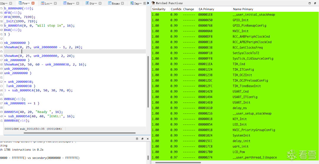
Select functions with high similarity to import into the bin file.
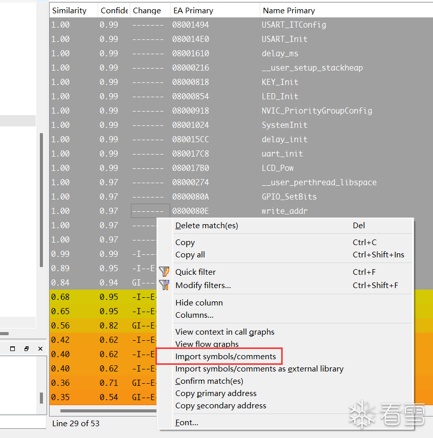
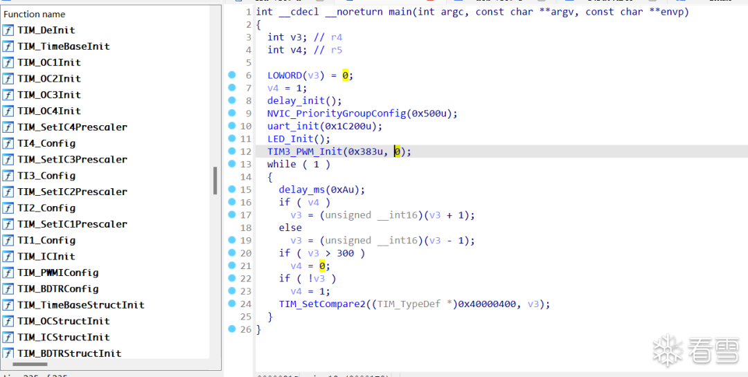
After importing, most function names can be restored.
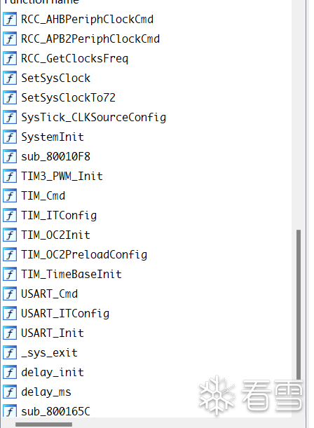
However, since my course project development used some initialization functions wrapped by XX Atomic (equivalent to secondary development of the original library functions), such as uart_init and delay_init, the restored functions will be slightly more than usual.
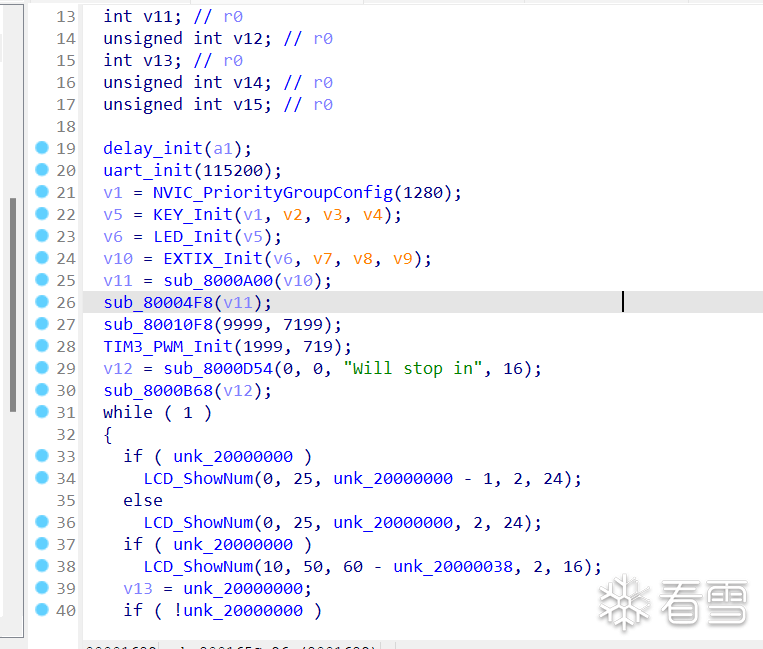
After using several idb files for recovery, it is now readable.
5
Import SVD Files, Restore Peripheral Structures
But this is not enough; we also need to import SVD files. What is an SVD file?
Since IDA 7.5, it has included a plugin for loading SVD files, as shown in the following image:
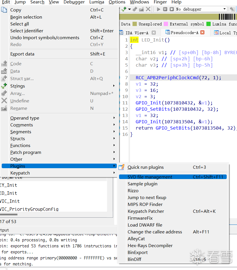
After opening, it will look like this:
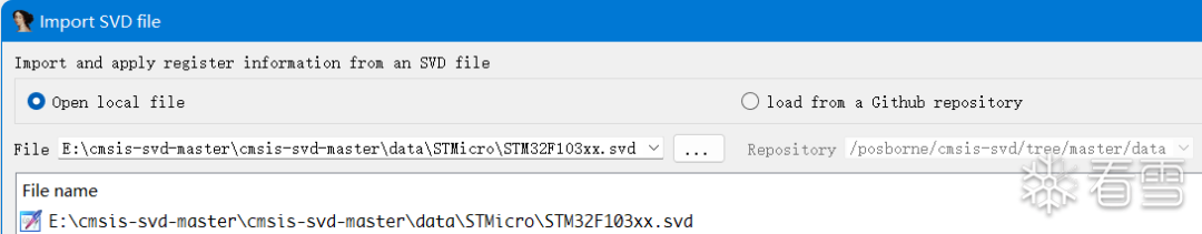
We can download the corresponding SVD file ourselves or load it from a GitHub repository. I chose to download it myself and load it locally. The download link is: cmsis-svd After selecting the SVD file you want to load, IDA will automatically restore the peripheral structures in the bin file, reflected in the pseudocode as follows:
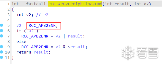
Like this:

Of course, not all peripherals can be restored, and there will definitely be differences from those in the axf file, but it has greatly aided our reverse engineering.
So far, we have completed the following steps: load the bin file -> set firmware loading base address -> add SRAM segment -> restore symbol table -> restore peripheral information. The program restoration work is nearing completion, with only one last step remaining: restoring structures.
6
Restore Structures
Open an example axf file to check the structures used within it.
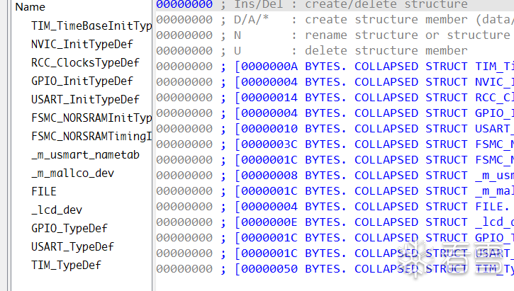
Among these structures, TIM_TimeBaseInitTypeDef, NVIC_InitTypeDef, GPIO_InitTypeDef, USART_InitTypeDef, GPIO_TypeDef, etc., are commonly used for timer initialization, interrupt initialization, IO port initialization, and so on.
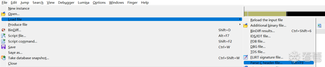
We generate a C header file.

Then parse the generated header file in the bin file:
Then in the local type, we can see many structures.

Simply importing the structures is not enough; we also need to manually reset the variable types in IDA’s pseudocode. How to determine the type of a variable? We need to refer to the variable types of the library functions for this.
Taking the GPIO_Init function as an example:
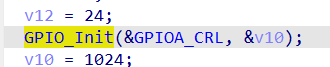
We open the firmware library user manual and find the prototype of GPIO_Init.
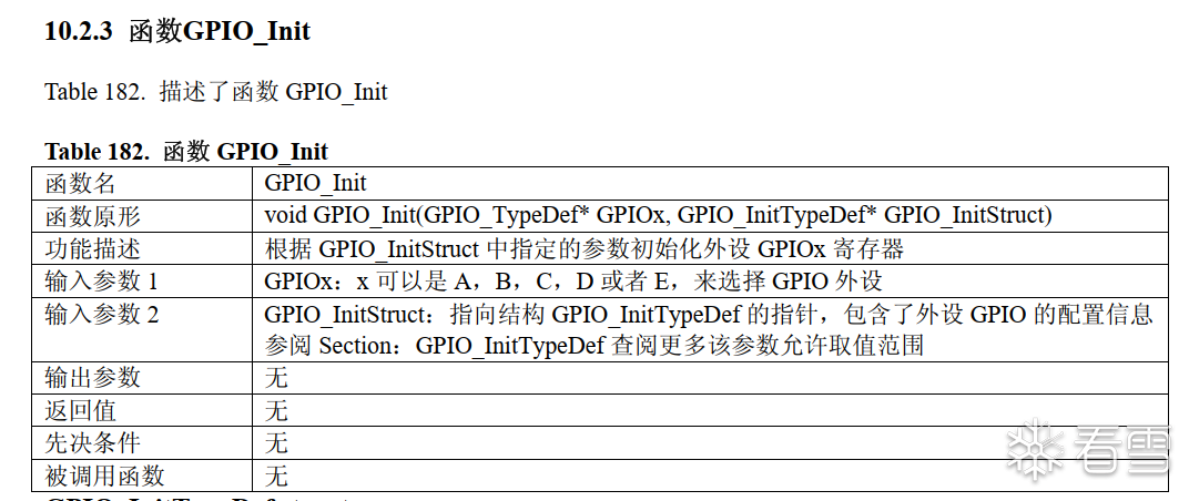
We can see the prototype is:
void GPIO_Init(GPIO_TypeDef* GPIOx, GPIO_InitTypeDef* GPIO_InitStruct)The second parameter is of type GPIO_InitTypeDef, so we modify the type of variable v10 in the pseudocode to GPIO_InitTypeDef. We can restore the remaining structures in the same way, as long as we have the firmware library functions, we can restore the corresponding structures. The effect is as follows:

The effect is quite good.
7
Conclusion
This reverse engineering is based on a small course project of mine, which has limited functionality, and since my project utilized some secondary development libraries from XX Atomic, the axf file I used to restore the symbol table was also compiled from XX Atomic’s examples, resulting in a higher ratio of restored symbol tables. If we can determine the chip model and whether the firmware library or HAL library is used, then this method can generally restore the firmware to a certain extent, greatly increasing its readability.
This experiment mainly serves as a starting point. If it can provide some help to the masters, that would be best. If the masters have other methods, please feel free to share.
Reference Links
1.https://www.cnblogs.com/shangdawei/p/3349700.htm
2.https://github.com/posborne/cmsis-svd
3.https://www.hyun.tech/archives/mcu%E5%8D%95%E7%89%87%E6%9C%BA%E5%9B%BA%E4%BB%B6%E9%80%86%E5%90%91%E5%88%86%E6%9E%90%E5%85%A5%E9%97%A8
4.https://www.alldatasheetcn.com/
5.https://blog.csdn.net/as480133937/article/details/87608816

KX ID: Lpwn
https://bbs.pediy.com/user-home-865862.htm
# Recommended Past Issues
1. Introduction to PWN – Format String Vulnerability
2. Tencent Game Security Technology Competition Question PC First Question 2016
3. Android APP Vulnerability Battle – Detailed Explanation of Debugging and Anti-Debugging
4. Fuzzm: Fuzz Testing for WebAssembly Memory Errors
5. 0rays Team 2021 Christmas On-Campus Recruitment Question Solution
6. 2022 Tencent Game Security Preliminary Question Analysis


Share the Ball

Like the Ball

Watching the Ball

Click “Read the Original” to learn more!