This issue’s topic:
More and more embedded devices now support remote automatic upgrades, eliminating the need for a downloader. This greatly facilitates device maintenance.
To enable remote upgrades, it is necessary to write program code that supports upgrades, which can be referred to as BootLoader.
This means dividing the device’s program code into two parts: BootLoader and APP.
BootLoader is responsible for upgrading the APP and booting the APP. The APP is responsible for implementing the core functional code of the device.
For Cortex-M series microcontrollers, to achieve safe jumping from BootLoader to APP, some configurations must be made.
This article uses the STM32 microcontroller as an example to discuss the key configuration steps to implement BootLoader jumping.
Discussion:
During the program development design phase, the Flash storage of the program should be partitioned based on the specific application.
This includes determining the storage location and the required space size for the BootLoader, as well as the storage location and size for the APP. This storage location directly affects the execution and jumping of the program.
The simplest upgrade scheme is: one BootLoader and one APP, where the BootLoader implements the jumping and upgrading functions of the APP. This article will introduce this upgrade scheme as an example.
For the STM32 microcontroller, the mapping address for program startup is 0x8000000.
The BootLoader can be stored at address 0x8000000, and the allocated space can be adjusted based on the specific Flash size of the chip. For example, 0x10000, which is 64K bytes.
The storage address for the APP is arranged behind the BootLoader, with the storage address being 0x8010000, and the remaining Flash space can be allocated to the APP.
BootLoader Project Configuration
The BootLoader project requires some configurations. Taking MDK as an example, as shown in the figure below, the FLASH address for the BootLoader program is 0x8000000, and its size is 0x10000.
When jumping to the APP, the following points need to be noted:
-
Check whether the stack top address is valid, that is, whether the starting address of the APP is valid,
<span>if(((*(__IO uint32_t *)APP_FLASH_ADDR) & 0x2FFE0000) == 0x20000000)</span>
-
Mask all interrupts to prevent exceptions caused by interrupt interference during the program jump
-
Obtain the starting address of the APP program, which is the second word of the code area (starting address + 4 for the data stored in Flash)
-
Initialize the stack pointer (the first word of the user code area is used to store the stack top address)
-
Using the APP starting address, convert it to a function pointer type and execute the jump
The specific jump code is as follows:
/* Define type */
typedef  void (*pFunction)(void);

/* APP flash address */
#define APP_FLASH_ADDR              (0x8010000)

void jump_to_app(void)
{
  uint32_t JumpAddress;
  pFunction Jump_To_Application;

  /* Check whether the stack top address is valid */
  if(((*(__IO uint32_t *)APP_FLASH_ADDR) & 0x2FFE0000) == 0x20000000)
  {
    /* Mask all interrupts to prevent exceptions during the jump */
    __disable_irq();

    /* The second word of the user code area is the program start address (reset address) */
    JumpAddress = *(__IO uint32_t *) (APP_FLASH_ADDR + 4);

    /* Initialize user application's Stack Pointer */
    /* Initialize APP stack pointer (the first word of the user code area is used to store the stack top address) */
    __set_MSP(*(__IO uint32_t *) APP_FLASH_ADDR);

    /* Type conversion */
    Jump_To_Application = (pFunction) JumpAddress;

    /* Jump to APP */
    Jump_To_Application();
  }
}
APP Project Configuration
The APP project also requires some configurations. Taking MDK as an example, as shown in the figure below, the FLASH address for the APP program is 0x8010000, and its size is 0x30000.
The APP program code needs to be configured as follows:
-
Modify the APP internal Flash vector table relocation
<span>SCB->VTOR</span>
-
After the APP runs, in the initialization function, enable interrupts; otherwise, the program will run abnormally
Normally, in the startup file, the function <span>SystemInit()</span> is called, which will configure the Flash interface information. <span>SCB->VTOR = FLASH_BASE | VECT_TAB_OFFSET</span>.
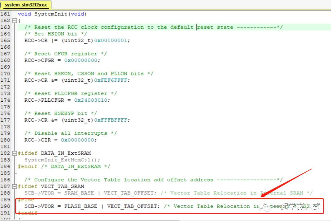
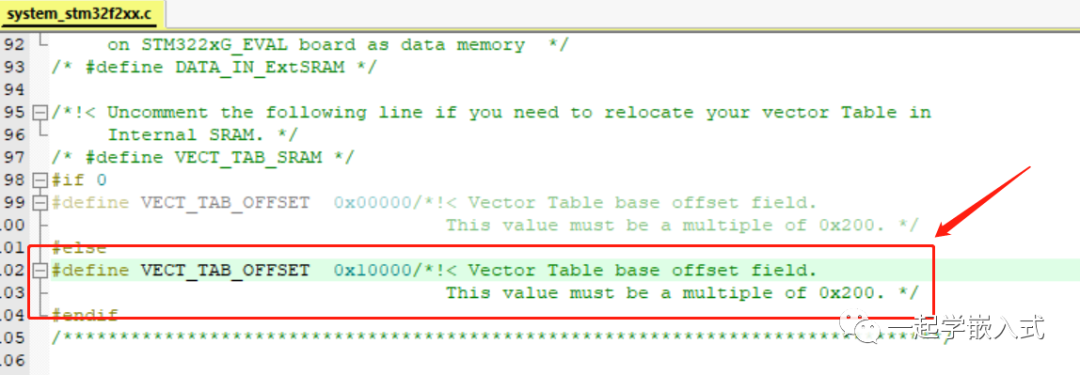
Modify the value of the macro definition <span>VECT_TAB_OFFSET</span> to 0x10000.
After the APP program starts, it is necessary to enable global interrupts first. The following code can be placed in the initialization section:
/* Enable interrupts */
__enable_irq();
During the device’s operation, the APP runs to handle business functions. To upgrade the APP, it is necessary to switch from the APP to the BootLoader.
So, how can the APP jump to the BootLoader? There are two methods:
-
Hardware method, power off the device to restart or reset button
-
Software method, reset the MCU through software control
For the software method, control instructions can be added in the APP code. When the APP receives a jump command (or an upgrade command), it resets the MCU. The following code can reset the MCU:
/* Reset chip */
HAL_NVIC_SystemReset();
Source: Learning Embedded Together
Copyright belongs to the original author. If there is any infringement, please contact to delete.
C Language, Circular Queue
ARM Processor Bootloader Low-level Process
Understand the differences between hex files, bin files, and axf files in one article
→ Follow for more updates ←


