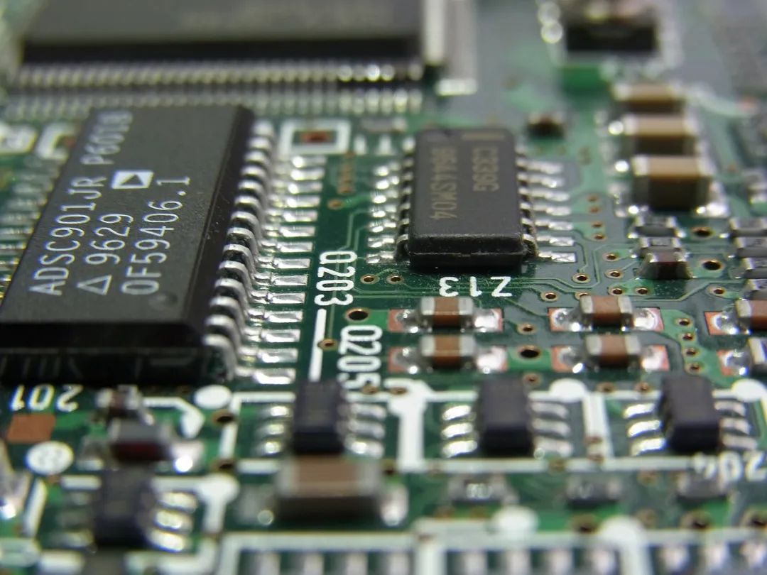
With the rapid development of electronic technology, high-speed DSP systems have become core components in many fields. However, in practical applications, the complex electromagnetic compatibility environment and high-temperature conditions can severely impact system stability. Therefore, how can we effectively design the electromagnetic compatibility and heat dissipation of high-speed DSP systems?

1. Electromagnetic CompatibilityElectromagnetic compatibility is critical for electronic devices to operate normally in complex electromagnetic environments. In high-speed DSP systems, the design of electromagnetic compatibility mainly involves the following aspects: ① Wire design: Choosing an appropriate wire width is key to reducing electromagnetic interference. Short and wide wires help lower inductance, thereby suppressing interference caused by transient currents. Especially for clock leads and bus driver signal lines, using short and wide wires should be prioritized. ② Wiring structure: Adopting a grid mesh wiring structure helps reduce electromagnetic interference. By performing lateral and vertical wiring on adjacent layers, the distributed capacitance and inductance between loops can be effectively reduced, thereby minimizing electromagnetic interference.
2. Heat Dissipation DesignIn high-speed DSP systems, heat dissipation design is equally critical. Effective heat dissipation design ensures that the system operates stably in high-temperature environments. Specific measures include: ① Stand-alone installation: Self-supporting installation of the printed circuit board aids in heat dissipation. By increasing the spacing between boards, air convection can be enhanced, thus accelerating heat dissipation; ② Component layout: A reasonable component layout is crucial for heat dissipation. In the horizontal direction, high-power components should be arranged near the edge of the printed circuit board to shorten the heat transfer path; in the vertical direction, high-power components should be placed as close as possible to the top of the printed circuit board to minimize temperature impact on other components; ③ Sensitive component positioning: Components sensitive to temperature should be placed in cooler areas, avoiding placement directly above high-heat-generating components to prevent performance degradation or damage due to heat accumulation.