Based on the characteristics of LED high efficiency, low carbon, and energy saving, most LCD TVs and mobile phones on the market now use LEDs as the backlight source. At the same time, to meet the demand for high color gamut coverage of LED backlight sources, the industry is gradually introducing some new fluorescent materials with narrow half-wave widths, such as fluoride phosphors and quantum dot phosphors. To better understand the characteristics of these phosphor materials, we will briefly introduce and explain fluoride phosphors and their applications below.
First, before understanding and recognizing fluoride phosphors, we will introduce some basic knowledge related to LED light sources in backlight applications.
1. Introduction to Relevant Knowledge of LCD
LCD: Short for Liquid Crystal Display, the full name of liquid crystal display screens, which include types such as TFT, UFB, TFD, STN, etc.
LCD TVs and mobile phones: TVs or mobile phones that use liquid crystal display screens as monitors.
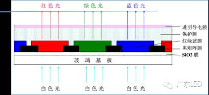
Taking the TFT type liquid crystal display as an example, its structure mainly includes a backlight source, light guide plate, upper and lower polarizers, liquid crystal, color filter, thin film transistors, etc. (see the structure diagram in Figure 1). The main structural functions are explained as follows:
(1) Backlight Source (Back Light): The imaging principle of LCD relies on liquid crystals blocking components of light to control brightness and darkness. A light source is essential for images to be seen on the screen, so the backlight source is responsible for providing the basic light source for the liquid crystal display.
(2) Light Guide Plate: Distributes light evenly across the entire screen.
(3) Up/Down Polarizer: The light emitted from the backlight source has inconsistent directional properties, appearing radial. If such light passes through the twisting of liquid crystal molecules, we still cannot see the desired image on the screen. At this point, the lower polarizer is responsible for standardizing the direction of the light before sending it to the liquid crystal layer.
(4) Thin Film Transistor (TFT): Controls the twisting angle of the liquid crystal molecules.
(5) Liquid Crystal: This layer of liquid crystal molecules twists under the control of TFT, thereby controlling the brightness of the light reaching the subsequent pixel units.
(6) Color Filter: After white light passes through the filter, we can see the light corresponding to the color of the filter. Thus, the function of the color filter in liquid crystal displays is to add color.
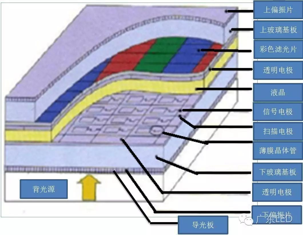 ▲ Figure 1 Structure Diagram of LCD
The imaging principle of LCD is to place liquid crystals between two pieces of conductive glass, controlling the twisting of liquid crystal molecules through the electric field driven by the upper and lower polarizers and electrodes, thus controlling the transmission or blocking of the backlight source, while combining other control and auxiliary functional layers to achieve the function of restoring the image.
Since liquid crystals require an additional light source to emit light, commonly used backlight sources for LCDs include CCFL (Cold Cathode Fluorescent Lamp), LED (Light Emitting Diode), HCFL (Hot Cathode Fluorescent Lamp), VFD (Flat Fluorescent Lamp), EL (Electroluminescent Sheet), OLED (Organic Electroluminescent Sheet), etc. Among these, CCFL is currently the most commonly used LCD backlight source, often referred to as traditional backlight sources.
Comparison of CCFL and LED:
CCFL – Made from hard glass and tricolor phosphors, containing a suitable amount of mercury and inert gas, with the inner wall coated with phosphor, and each end having an electrode. The disadvantage is the limited color representation.
LED – A semiconductor solid light-emitting device that uses solid semiconductor chips as the emitting material. In the semiconductor, excess energy is released through the recombination of carriers, resulting in photon emission, directly emitting red, yellow, blue, green, cyan, orange, purple, and white light. Because LED light-emitting diodes have good color representation, they have completely replaced traditional cold cathode fluorescent tube light sources.
2. Knowledge Related to Color Gamut Coverage
Color gamut coverage: The horseshoe-shaped color triangle marked with colors on the CIE-xy chromaticity diagram represents the color area visible to the human eye. If a certain system can reproduce all colors within this horseshoe area, it can be said to have a color gamut coverage of 100%. When reproducing colors using the three primary colors R, G, and B, the triangular area formed by the coordinates of these three primary colors represents the color reproduction area determined by these three colors. The ratio of this area to the horseshoe area is the color gamut coverage. Therefore, color gamut coverage is the ratio of the area of the triangle formed by the coordinates of the three primary colors R, G, and B to the area of the triangle formed by the standard RGB coordinates.
In different fields, the requirements for the standard R, G, and B coordinates vary, which involves different color gamut evaluation standards. Common standards for color gamut include NTSC, ITU-R BT.709, sRGB, Adobe RGB, ITU-R BT.1361, xvYCC, etc. Below is a brief introduction to three commonly used standards (sRGB, NTSC, and Adobe RGB):
(1) NTSC Standard: Established in 1953 by the National Television Standards Committee (NTSC) based on the CIE1931 chromaticity diagram, this standard is also commonly used in China.
(2) sRGB Standard: A color gamut standard for digital imaging established by the International Electrotechnical Commission (IEC) in 1996, primarily applied in digital image acquisition devices, but not yet fully popularized on monitors.
(3) Adobe RGB Standard: Proposed by Adobe in 1998, with a color space broader than sRGB, generally used in printing, publishing, and image processing fields.
The white light positions, color temperatures, and RGB primary color coordinates of sRGB, NTSC, and Adobe RGB are shown in Table 1:
▼ Table 1 Relevant Parameters of sRGB, NTSC, and Adobe RGB Standards
|
sRGB |
NTSC |
Adobe RGB |
|
|
White Light Position |
(0.3127, 0.3290) |
(0.3101, 0.3162) |
(0.3127, 0.3290) |
|
Color Temperature |
6507K |
6766K |
6507K |
|
R |
(0.6400, 0.3300) |
(0.6700, 0.3300) |
(0.6400, 0.3300) |
|
G |
(0.3000, 0.6000) |
(0.2100, 0.7100) |
(0.2100, 0.7100) |
|
B |
(0.1500, 0.0600) |
(0.1400, 0.0800) |
(0.1500, 0.0600) |
In this article, the color gamut referred to is the NTSC standard color gamut, abbreviated as NTSC color gamut.
Combining the concept of color gamut coverage, we can deduce that the NTSC color gamut is the ratio of the area of a triangle formed by certain RGB primary color coordinates to the area of a triangle formed by the standard RGB coordinates (as illustrated in Figure 2). The higher the ratio, the better the color representation.
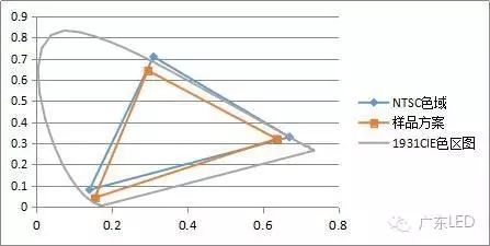 ▲ Figure 2 Illustration of Color Gamut Coverage
Based on the concept of color gamut coverage and its evaluation standards, we can infer that the key factors affecting its value are the RGB primary colors (i.e., backlight source, with white LED as the focus in this article), CF, and standard RGB coordinates. The known factors are the standard RGB coordinates under NTSC, CF, thus the key factor becomes the backlight source.
Basic knowledge of CF:
CF is actually composed of R, G, and B filters (as shown in the planar diagram 3), and only light sources with spectra close to the filter can better pass through the filter. At this time, the NTSC value of that light source is higher.
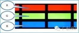 ▲ Figure 3 Planar Diagram of CF
 ▲ Figure 4 Illustration of CF to Light Conversion
White LED light after passing through CF obtains another new white light spectrum, which is actually composed of three independent R, G, and B spectra. The detailed process is shown in the diagram below:
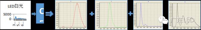 ▲ Figure 5 Spectrum Illustration of White LED after CF
The characteristics of a certain CF model can be represented by a curve (Figure 6), which is actually composed of three individual curves of R, G, and B (Figure 7). Each curve can be simply understood as follows:
The curve – Peak value around 650nm, bandwidth distribution from 570-780nm, indicates that light in the 570-780nm band can pass through, while other bands will be filtered out. Meanwhile, in the passable 570-780nm band, the proportion of energy intensity that can pass through also varies due to wavelength differences.
The curve – Peak value around 530nm, bandwidth distribution from 465-615nm, indicates that light in the 465-615nm band can pass through, while other bands will be filtered out;
The curve – Peak value around 460nm, bandwidth distribution from 400-520nm, indicates that light in the 400-520nm band can pass through, while other bands will be filtered out;
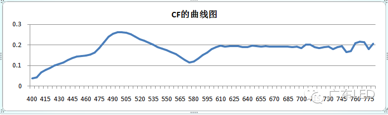 ▲ Figure 6 CF Curve Diagram
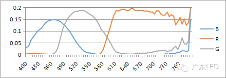 ▲ Figure 7 CF Curve Decomposition Diagram
Table 2 shows the R, G, and B parameters of a commonly used type A CF from Ruifeng Optoelectronics:
▼ Table 2 R, G, B Parameters of Type A CF
|
R |
G |
B |
|||
|
Peak Value |
Half Width |
Peak Value |
Half Width |
Peak Value |
Half Width |
|
653 |
188 |
531 |
99 |
463 |
94 |
From the CF curve decomposition diagram, it can be seen that under the NTSC standard, to achieve a high NTSC value for the LED backlight source passing through CF, the RGB peak values that make up white light should be close to the RGB peak values of the CF, and the half widths of the RGB colors in white light should be as narrow as possible.
3. Knowledge Related to High Color Gamut Coverage
It is known that the NTSC color gamut is the ratio of a triangular area under the NTSC standard to the area of the standard triangular area. The higher the ratio, the better the color representation. The high color gamut coverage commonly referred to in the industry indicates that the NTSC color gamut ratio is ≥85%. The following table shows the common methods to achieve different NTSC values of white light.
▼ Table 3 Common Methods to Achieve Different NTSC Values of White Light
|
NTSC Value |
Method to Achieve White Light |
|
70% |
YAG Yellow Phosphor |
|
Silicate Yellow Phosphor |
|
|
75% |
540β-SiAlON+630Nitride |
|
80% |
540β-SiAlON+650Nitride |
|
85% |
540β-SiAlON+630 Fluoride |
|
95% |
529β-SiAlON+630 Fluoride |
From the factors affecting color gamut coverage, it can be seen that under the NTSC standard, the key factor affecting the color gamut value is the LED backlight source. The commonly used high color gamut coverage white light is generally achieved by blue light chips + green phosphors + red phosphors. Combining the principle of white light passing through CF, it can be concluded that the key to achieving high color gamut coverage lies in the selection of green and red phosphors, with the key influencing factors being the physical parameters (peak values, half widths) of the green and red phosphors and their matching with CF. The following table shows the peak wavelengths and half widths of different types of LED phosphors. Based on the mass production and application status of phosphors in the LED industry, the best solution for achieving high color gamut coverage currently involves using β-SiAlON for green phosphors and fluoride for red phosphors.
▼ Table 4 Peak Wavelengths and Half Widths of Different Types of LED Phosphors
|
Phosphor System |
Powder Color |
Peak Wavelength (nm) |
Half Width (nm) |
|
YAG |
Y |
550-570 |
115-120 |
|
Ga-YAG |
G |
530-545 |
110-115 |
|
LuAG |
G |
525-540 |
105 |
|
Silicate |
G |
510-530 |
60-70 |
|
Y, O |
540-600 |
80-95 |
|
|
β-SiAlON |
G |
530-540 |
48-55 |
|
Nitride (1113) |
R |
615-660 |
75-95 |
|
Fluoride |
R |
630 |
<30 |
|
Quantum Dot |
B |
410-460 |
<30 |
|
G |
510-550 |
<40 |
|
|
R |
590-640 |
<40 |
4. Basic Knowledge of Fluoride Phosphors
Fluoride is a fluorosilicate excited by tetravalent manganese, with the molecular formula AxMFy:Mn4+ (where A=Li, Na, K, Ca, Sr, Ba, etc., M=Si, Al, Y, Sc, etc.). Commonly used fluoride phosphors generally include three systems: KSF, KGF, and KTF, where KSF belongs to the cubic crystal system, and KGF and KTF belong to the hexagonal crystal system (as shown in the lattice diagram below), with the Chinese names being: potassium/germanium/titanium silicate excited by tetravalent manganese, with chemical formulas K2SiF6:Mn4+, K2GeF6:Mn4+, and K2TiF6:Mn4+, whose chemical formulas are similar to silicates (silicate chemical formula: XSiO2).
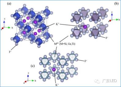 ▲ Figure 8 Lattice Diagram of Fluoride
Powder characteristics: fixed peak wavelength (630nm), narrow half width (<30nm), and the powder appearance color is orange.
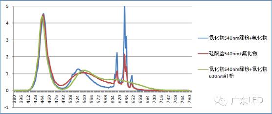
Based on the above powder characteristics, in practical applications, fluoride red phosphors are often paired with green phosphors of the same wavelength, which results in a higher NTSC than that of the same wavelength nitride red phosphors. The emission spectrum of fluoride phosphors compared to that of nitride red phosphors of the same wavelength is shown below:
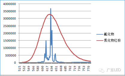 ▲ Figure 9 Emission Spectrum Diagram of Fluoride and Nitride Red Phosphors
Stability: Fluoride phosphors have an unstable structure and are hygroscopic, a characteristic similar to silicates. Additionally, fluoride phosphors are prone to decompose and generate toxic HF gas when the temperature rises, a reversible reaction. When encountering water, the powder’s appearance color changes from orange to brown (as shown in Figure 10), with the chemical reaction formula:
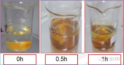 ▲ Figure 10 Color Change Diagram of Fluoride after Reaction with Water
Fluoride phosphors are not heat resistant. In a short time, as the temperature increases, the brightness of the phosphors decreases, and under conditions above 150℃, the decrease accelerates. However, this reaction is reversible, and the change curve is shown below:
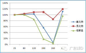 ▲ Figure 11 Temperature Resistance Curve of Fluoride Powder
5. Application Scheme Description
Fluoride Phosphors in High Color Gamut Coverage
In practical applications, fluoride is often paired with nitride green phosphors for LED products with high NTSC requirements (NTSC≥85%).
The following table compares the optical color parameters of fluoride phosphors and conventional phosphors after packaging:
▼ Table 5 Optical Color Parameters of Fluoride Phosphors and Conventional Phosphors after Packaging
|
Phosphor Pairing |
NTSC |
Brightness |
|
|
540nm Nitride |
Fluoride Phosphor (630nm) |
88% |
100% |
|
540nm Nitride |
Nitride Red Phosphor (630nm) |
75% |
90% |
|
540nm Silicate |
Fluoride Phosphor (630nm) |
82% |
103% |
|
540nm Nitride |
Fluoride Phosphor (630nm) |
88% |
100% |
|
530nm Nitride |
660nm Nitride Red Phosphor |
88% |
75% |
|
530nm Silicate |
Fluoride Phosphor (630nm) |
88% |
97% |
Note:
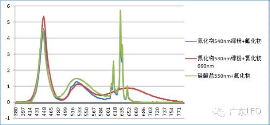
(1) Due to the narrow half width, when fluoride is paired with green phosphors of different materials in the same wavelength, it has a higher NTSC;
(2) Due to the narrow half width, the secondary absorption of light is reduced. Under the same NTSC effect, the fluoride solution has higher brightness;
▼ The following is an illustration of the white light spectrum:
6. Patent Status of Fluoride Phosphors Applications
Material Patents: In 1972, Osram and GE publicly reported fluoride materials, theoretically, there are no patent issues with fluoride materials themselves.
Application Patents: The original application patent for fluoride is owned by GE, with the main patent being US7497973B2, applied for on February 28, 2006, which is a patent for the combination of powder and chips, with applications in Europe, Japan, and the United States, all of which have been authorized. At the same time, Nichia also claims to own relevant patents, but the specific status needs to be verified.
7. Precautions for the Application of Fluoride Phosphors
Fluoride phosphors have characteristics of being hygroscopic and not heat-resistant. Currently, these defects can only be mitigated through coating technology to delay the damage caused by humidity and temperature, and cannot be completely resolved. Therefore, in the application of fluoride, it is necessary to match with materials that have good airtightness and heat dissipation, especially in the selection of brackets and packaging adhesives. Moreover, fluoride should not be used in environments with temperatures above 150℃. At the same time, packaging manufacturers should obtain application patent authorization from GE when using fluoride phosphors for device packaging, otherwise, it may easily infringe GE’s packaging application patents.
8. Conclusion
In summary, due to the narrow half-width characteristics of fluoride, it has advantages of high color gamut coverage and high brightness in LCD backlight applications. However, due to its structural defects, we need to pay special attention to the selection of other packaging materials in application. When the packaging materials are reasonably matched, it is possible to achieve high color gamut coverage, high brightness, and high reliability.

– Guangdong LED –
Discover New Ways of Semiconductors
QQ: 1789064241
Inscribed by Song Hai, then Vice Governor of Guangdong Province, supervised by the Guangdong Provincial Science and Technology Department, jointly managed by the science and technology bureaus of eight cities, co-sponsored by the Guangdong Provincial Semiconductor Lighting Industry Innovation Center, Guangdong Semiconductor Light Source Industry Association, and Shenzhen LED Industry Association (5A level).
↓↓↓ Click “Read Original” [China Packaging and Equipment Technology Innovation Summit Forum