1. Embedding Assembly Language in C
In microcontroller development, we usually write the main program in C language, which allows us to fully utilize the mathematical libraries and powerful data processing capabilities provided by C language tools. However, the controllability of C language is not as good as that of assembly language. For some time-sensitive operations, we still need to use the more flexible assembly language. This leads to the problem of mixed programming in C and assembly language, which can be divided into three methods: 1. Assembly language calls C language functions; 2. C language calls assembly language; 3. Embedding assembly language in C. Here, we mainly introduce the third method, which is embedding assembly language within C language.
The following program is the main program that calls a precise 205μS delay subroutine and toggles the output of P1.0 between high and low levels to generate a square wave.
/*————Program Name: test.c————*/
#include
// Crystal frequency 12.000MHz
/****************/
void delay(void) // Delay 205μS
{
#pragma asm
MOV R0, #100
LOOP:
DJNZ R0, LOOP
#pragma endasm
}
/***************/
void main(void) // Main function, which toggles P1.0 between high and low levels
{
while(1)
{P1_0 = !P1_0;
delay();}
}
The specific implementation process is as follows:
1. First, write a delay program in assembly language, compile it in the Keil development environment, and then perform software simulation. The crystal frequency setting should match your requirements. During simulation, pay attention to the time display in the left register window and adjust the parameters of the delay program to obtain the precise delay we need.
2. Use C51 to write the main program and the shell of the delay subroutine (waiting to embed assembly language), assuming this program is named test.c.
3. Insert the assembly delay subroutine obtained in step 1 into the shell of the delay subroutine written in C51. Note to add #pragma asm and #pragma endasm statements at the beginning and end, respectively. This method tells the C51 compiler through asm and endasm that the lines in between should not be compiled into assembly lines.
4. According to Keil’s usage method, create a project file and add the source program.
5. Click on the C source program containing the assembly program, then right-click, and select Options for File ‘test.c’ from the dropdown menu (Figure 1). This will bring up the interface shown in Figure 2. Check Generate Assembler SRC File and Assembler SRC File to make them effective.
6. Load the encapsulated library file according to the project’s compilation mode, usually C51S.LIB in Small mode (this file is located at C:\Keil\C51\Lib\C51S.LIB), see Figure 3 for details.
7. Click Rebuild target to get the compilation result (Figure 4).
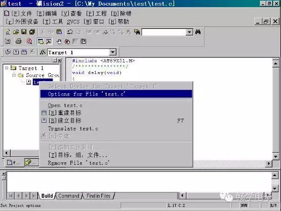
Figure 1
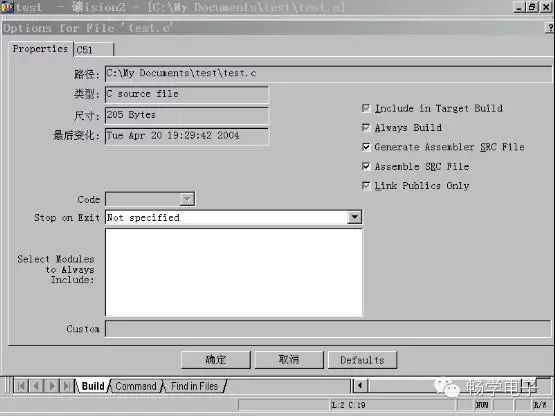
Figure 2
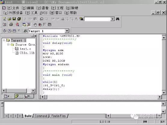
Figure 3
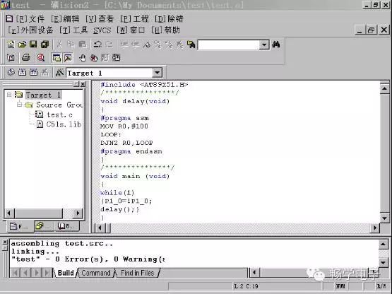
Figure 4
2. Extending External Interrupts with Software
As we know, the 51 microcontroller has only 2 external interrupts. A method for extending external interrupt sources has been introduced in books, but it requires additional hardware costs (see Figure 5). By introducing an external interrupt source input terminal (/INT0 or /INT1) through an OR gate, it can also be connected to a certain I/O port. In this way, each “source” can trigger an interrupt, and the interrupt service program can determine which one is the requesting interrupt source through software polling, with the polling order determined by the interrupt source priority. This allows for the extension of multiple external interrupt sources.
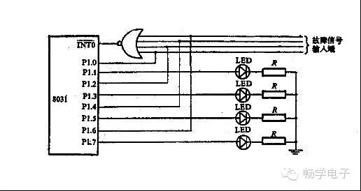
Figure 5
Although this method extends external interrupt sources, it also has its downsides. For example, designing a circuit with 8 interrupt sources would require an 8-input OR gate, which is clearly not beneficial for size and cost. Here, I will introduce a method I designed to extend external interrupt sources, which is implemented purely in software without adding any components (see Figure 6).
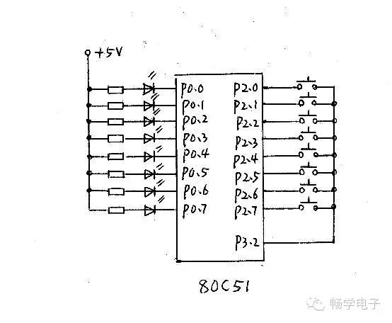
Figure 6
#include
static unsigned char data m; // m is a global variable
/*——-Delay Subroutine——-*/
void delay(unsigned int k)
{
unsigned int i, j;
for(i = 0; i
for(j = 0; j < 121; j++)
{;}
}
}
/*—External Interrupt INT0 Subroutine—*/
void init0() interrupt 0
{
delay(10); // Delay 10ms to debounce
if(P3_2 == 0)
{
EX0 = 0; // Disable INT0 interrupt
EA = 0; // Disable global interrupt
P3_2 = 0; // Set P3.2 to low level
P2 = 0xff; // Set P2 port to all 1s
m = P2; // Read P2 port state into m
P2 = 0x00; // Restore P2 port to all 0s
P3_2 = 1; // Set P3.2 to high level
IT0 = 1; // Set INT0 to edge-triggered
EX0 = 1; // Enable INT0 interrupt
EA = 1; // Enable global interrupt
}
}
/********Main Program*********/
void main(void)
{
P2 = 0x00; // Set P2 port to all 0s
P3_2 = 1; // Set P3.2 to high level
IT0 = 1; // Set INT0 to edge-triggered
EX0 = 1; // Enable INT0 interrupt
EA = 1; // Enable global interrupt
while(1) // Infinite loop
{
P0 = m; // Output the content of global variable m to P0 port
P3_0 = !P3_0; // Toggle P3.0 to indicate program status
delay(500); // Delay 500ms
}
}
Program Explanation: When no button is pressed, the LED on P3.0 flashes to indicate the program status. During the main program initialization, set the P2 port to all 0s, set P3.2 to high level, and configure INT0 to be edge-triggered while enabling interrupts. Any button press will trigger the INT0 interrupt, entering the interrupt service subroutine. First, disable interrupts, then set P3.2 to low level, set P2 port to all 1s, read the P2 port state into m, and by polling the status word of m, we can know which interrupt source is currently requesting. The method we use here is to output m to the P0 port to light up an LED as an indication. Upon exiting the interrupt, interrupts are re-enabled.