Click the “blue words” above to follow us!
2025.03.01
Word Count: 7268
Estimated Reading Time: 19 minutes
Part One
0 Introduction
As the complexity of embedded system software development continues to rise, embedded operating systems are increasingly being applied in software development. Currently, the main embedded operating systems used for MCUs are uC/OS, FreeRTOS, and RT-Thread. In microprocessors with MMUs, foreign embedded operating systems like Linux and VxWorks dominate the market, while domestic operating systems are almost nonexistent. In recent years, with the rapid development of the Internet of Things (IoT) industry in China and the increasing demand for domestic equipment to be self-controllable, this situation has begun to change, and the development of domestic embedded operating systems has entered an accelerated phase. RT-Thread has launched its latest hybrid microkernel architecture—RT-Thread Smart. RT-Thread Smart is primarily aimed at mid-to-high-end processors with MMUs, providing a more competitive operating system software platform for various fields.
Part Two
1 System Composition
The embedded real-time control system constructed in this article mainly consists of the RT-Thread Smart operating system and the hardware platform based on the STM32MP157 processor.
1.1 RT-Thread Smart Operating System

RT-Thread Smart is an embedded real-time operating system that supports multitasking and adheres to the Apache License 2.0 open-source licensing agreement. It can be used freely in commercial products without the need to disclose private code. It applies object-oriented design methods to real-time system design, resulting in a clear architecture, modular systems, and good scalability. Compared to the Linux operating system, RT-Thread is smaller in size, lower in cost, consumes less power, and has a faster startup speed. Additionally, RT-Thread features high real-time performance and low resource consumption, making it very suitable for various resource-constrained scenarios (such as cost and power consumption limitations). The 32-bit MCU is its primary operating platform, but in practice, many application processors with MMUs based on ARM9/ARM11 or even Cortex-A series CPUs also use RT-Thread. Compared to other real-time operating systems, it has a richer set of middleware components as a real-time kernel.
The RT-Thread kernel is the core part of RT-Thread, including the implementation of objects in the kernel system, such as multithreading and its scheduling, semaphores, mailboxes, message queues, memory management, timers, etc. The libcpu/BSP (chip porting related files / Board Support Package) is closely related to hardware and consists of peripheral drivers and CPU ports.
1.2 STM32MP157 Microprocessor
The STM32MP157 microprocessor is based on a flexible dual Arm Cortex-A7 core (operating frequency of 800 MHz) and a Cortex-M4 core (operating frequency of 209 MHz) architecture, equipped with a dedicated 3D graphics processing unit (GPU), a MIPI-DSI display interface, and a CAN FD interface. In addition to an LCD-TFT display controller, the STM32MP157 series also integrates up to 37 communication peripherals, including 10/100M or Gigabit Ethernet, 3 USB2.0 hosts/OTG, 29 timers, and advanced analog devices. In addition to a true random number generator (TRNG), hardware encryption, and hash processors, security options also include secure boot, TrustZone peripherals, and active tamper detection functions.
Part Three
2 Porting Overview
2.1 Operating System Structure
RT-Thread Smart is an operating system with a hybrid microkernel architecture, overall adopting a microkernel structure, supporting the execution of system services in kernel mode or user mode based on actual application scenarios. As an embedded operating system, its components can be roughly divided into the following parts: Bootloader, RTOS kernel, root file system, and APP, as shown in Figure 1.
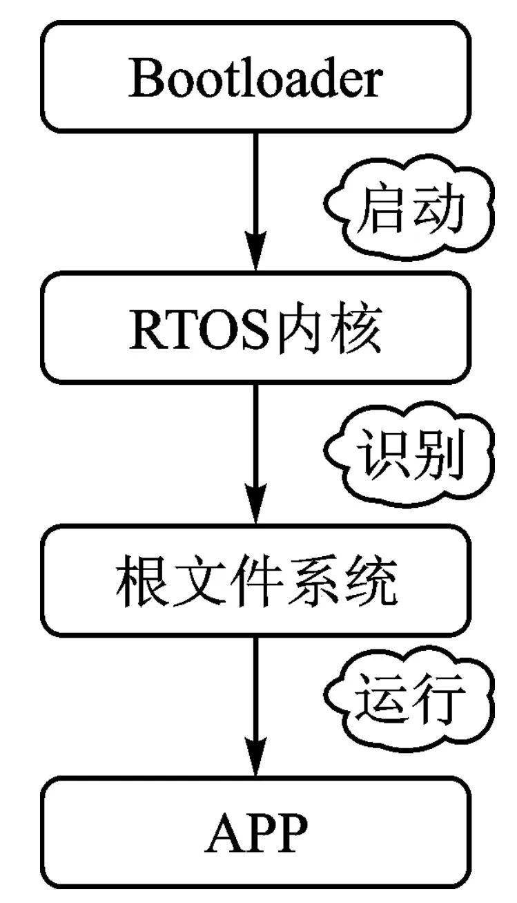
Figure 1 Composition of Embedded Software System
The Bootloader commonly used is u-boot, which prepares some startup parameters for the kernel in advance and stores them in memory. These parameters are used to complete the kernel startup. The porting part mainly aims to port the kernel, while the RTOS kernel refers to the kernel itself and the driver part, starting from the lower-level parts of the kernel, and then proceeding to the root file system and the APP that need to be executed for the system to run. A feature of RT-Thread is that it uses system calls to divide the entire system into user mode and kernel mode through the MMU, so the configuration of the MMU is an essential part, and it is also necessary to implement the serial port driver for printing as well as the timer driver to ensure that the system can use interrupts normally.
2.2 Compilation System
For various kernels, as long as they support the menuconfig configuration interface, they all use Kconfig. In the configuration interface, options can be selected or set, and these settings will be saved in the .config file. The compilation script will include the .config, which determines the files to be compiled and how to compile them based on the values inside. The .config file will also be converted into a header file, from which C programs can obtain configuration information. When executing the menuconfig command and entering the configuration interface to configure RT-Thread Smart, the configuration results are saved in the .config file and will be converted into the header file rtconfig.h. The rtconfig.h file contains each configuration item, such as:
# define RT_TICK_PER_SECOND 100
# define RT_USING_OVERFLOW_CHECK
# define RT_USING_HOOK
# define RT_USING_IDLE_HOOK
In the C file, the rtconfig.h file can be included to obtain this configuration information. The sample code is as follows:
# include <rtthread.h>#include <rthw.h>/* hard timer list*/Staticrt_list_t rt_timer_list[RT_TIMER_SKIP_LIST_LEVEL];#ifdef RT_USING_TIMER_SOFT# define RT_SOFT_TIMER_IDLE 1# define RT_SOFT_TIMER_BUSY 0#ifndef RT_TIMER_THREAD_STACK_SIZE# define RT_TIMER_THREAD_STACK_SIZE 512# endifWhere #include<rtthread.h> includes rtconfig.h, and the following #ifdef RT_USING_TIMER_SOFT also uses macros from the aforementioned header file. When using SCons for compilation, many SConscript script files will be obtained. SCons organizes the source code structure using SConscript and SConstruct files. Generally, a project has only one SConstruct file, but there will be multiple SConscript files. Typically, each subdirectory containing source code will have a SConscript. To better support various compilers and facilitate the adjustment of compilation parameters, RT-Thread creates a file named rt-config.py for each BSP. Therefore, each RT-Thread BSP directory will contain three files (rtconfig.py, SConstruct, and SCon-script), which control the compilation of the BSP. There is only one SConstruct file in a BSP, but there will be multiple SConscript files, so the SConscript files truly reflect the organization of the source code. In the SConscript, the built-in function GetDepend (macro) is used to specify the files to be compiled and the compilation parameters. It reads configuration information from the rtconfig.h file: if a certain macro in rtconfig.h is enabled, this function returns true; otherwise, it returns false.
Part Four
3 RT-Thread Smart Porting
After downloading the rt-smart.zip software package, the directory description can obtain the structure diagram shown in Figure 2.
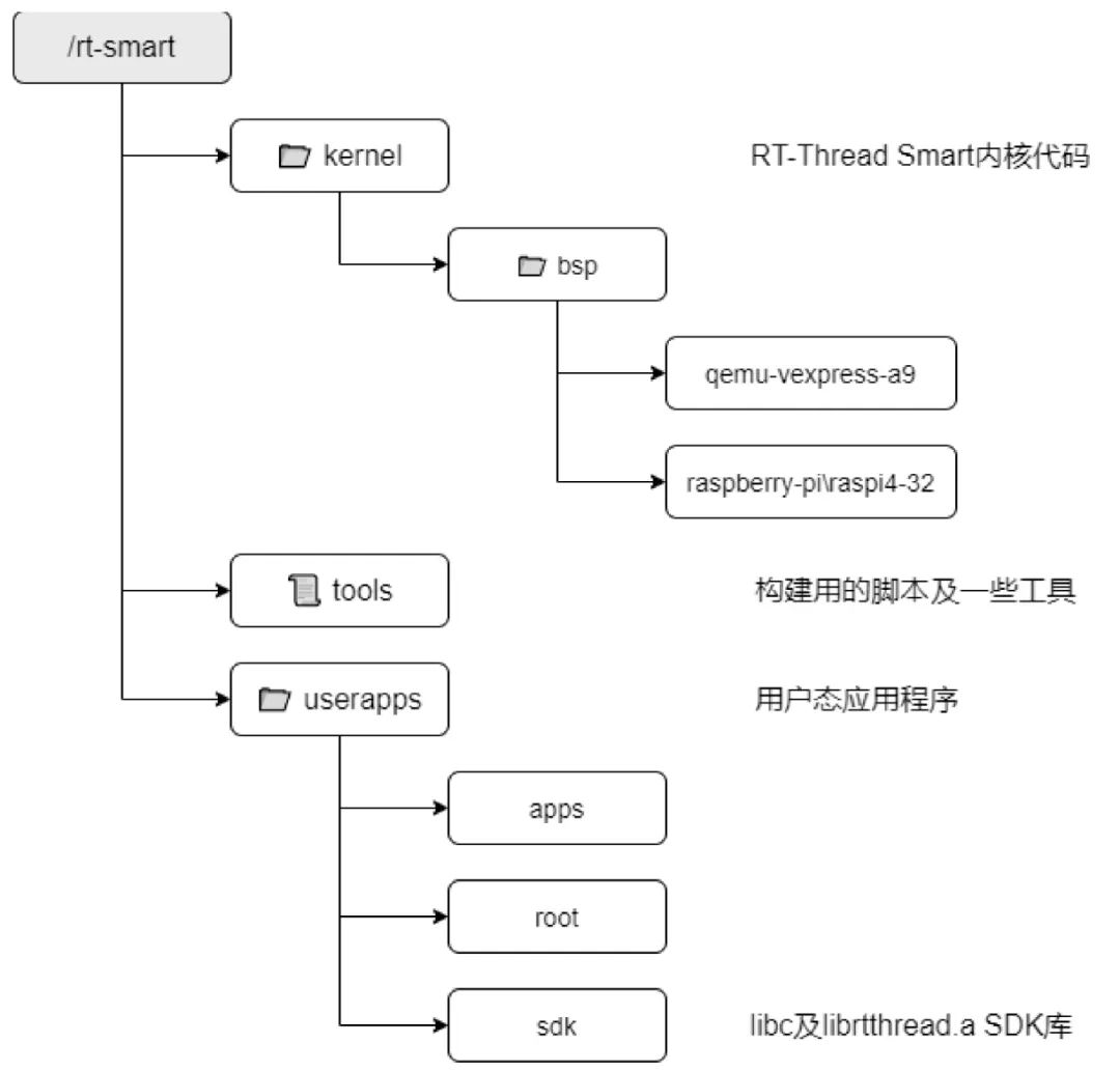
Figure 2 Structure Diagram of rt-smart.zip
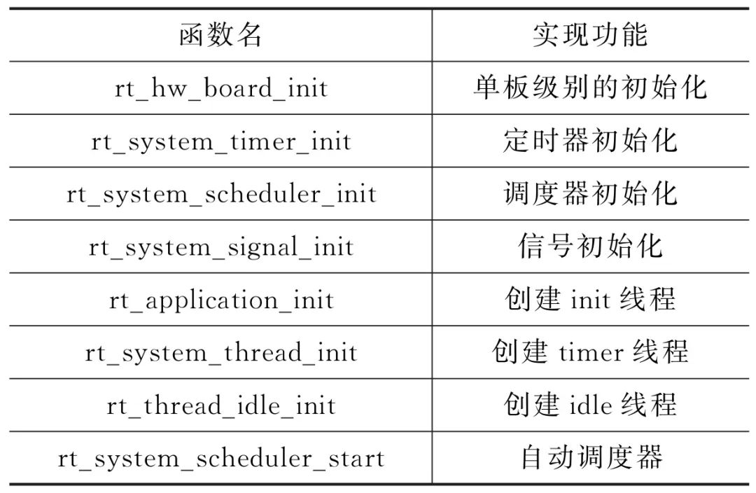
Figure 2 is the main framework of RT-Thread Smart. The porting work mainly involves the architecture of the CPU and bsp. The official source code already supports some chips; during porting, existing chip files can be utilized to add new chips, while other parts should not be modified excessively. The key to porting is ensuring that the kernel can start normally. The kernel startup is roughly divided into two parts: startup assembly and executing the rt-thread_startup function. During kernel porting, address mapping, interrupt controllers, serial port drivers, and timer drivers are involved. The entry points for the interrupt controller, serial port driver, and timer driver are all rtthread_startup, and the main work of the function is listed in Table 1.
Table 1 Work Involved in rtthread_startup Function
3.1 Adding the Board
From the structure diagram of the rt-smart.zip software package, it can be seen that the official source code of RT-Thread Smart mainly supports two chips: raspi4 – 32 and raspberry-pi. Based on the already supported chips, modify the files, enter kernel\bsp\stm32mp157, and modify the rtconfig.py file to ensure that the header of the compiled .bin file stores the location, size, and other compilation information of the file read into memory. The .bin file should be downloaded to 0xC0100000, modified as follows: POST_ACTION=OBJCPY+’-O binary $TARGET rtthread.bin
‘+SIZE+’$TARGET
‘+’mkimage -T stm32image -a 0xC0100000 -e 0xC0100000 -d rtthread.bin. After modification, open env.bat, enter the rt-smart directory, set the environment variable smart-env.bat, and enter rt-smart\kernel\bsp\stm32mp157 for compilation. The results are shown in Figure 3.
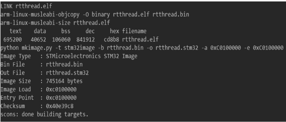
Figure 3 Compilation Success
3.2 Address Mapping
The memory is uniformly managed by the operating system, including the allocation, recycling, and swapping of physical memory pages. In this structure, the memory controller is responsible for monitoring the update status of PCM physical pages while also sending interrupt prompts to the CPU. The operating system is responsible for interrupt handling, bringing frequently updated pages into memory. Embedded operating systems with MMUs are not significantly different from general systems in terms of finding physical addresses.
For example, for two-level page table mapping, the CPU issues a virtual address vaddr, and the MMU finds the first-level page table entry based on the vaddr, then finds the specific physical address corresponding to the entry in the second-level page table. The address is retrieved from this entry, assuming it is address, and then the value corresponding to this physical address in memory is found. During kernel porting, it is essential to consider the position of the kernel in memory and to know the physical information of DDR. When processing memory mapping, the PV_OFFSET must be determined based on the chip manual. According to the chip manual, the starting address of DDR is 0xC0000000 and the ending address is 0xE0000000, totaling 512 MB. The virtual base address of memory is: KERNEL_VADDR_START=0xC0000000, so PV_OFFSET=0xC0000000-0xC0000000=0, and finally configure PV_OFFSET in menuconfig.
When determining the memory size based on the resources of the board, it is necessary to modify the plateform_mem_desc array’s vaddr_end. Since the size of DDR is 512 MB (i.e., 0x20000000), the code 0x0FFFFFFF should be changed to 0x1FFFFFFF. After completing the address mapping, it is also necessary to set the GIC (Generic Interrupt Controller), which handles interrupts from various modules such as GPIO and UART, sending them to the GIC, which then forwards them to a specific Processor. The internal structure of the GIC can be divided into two parts: 1) the Distributor, which connects all interrupt sources in the system, and can control the properties of each interrupt source through the arbitration unit’s registers, such as priority, status, security, routing information, and enable status. The distributor outputs interrupts to the CPU interface unit, which decides which interrupt to forward to the CPU core. 2) The CPU Interface Unit, where the CPU core receives interrupts through the controller’s CPU Interface Unit. The registers of the CPU Interface Unit are used to mask, identify, and control the status of interrupts forwarded to the CPU core. Each CPU core in the system has a separate CPU interface. Interrupts are identified in software by a number called the interrupt ID, and each interrupt source has its own ID. Software can use the interrupt ID to identify the interrupt source and call the corresponding handler to process the interrupt. The interrupt ID presented to software is determined by system design and is generally recorded in the SoC data manual. For RT-Thread Smart that already supports GIC, it is necessary to set the physical address. The implementation code is as follows:
# define REALVIEW_GIC_CPU_BASE 0xA0022000/* Generic interrupt controller CPU interface */# define REALVIEW_GIC_DIST_BASE 0xA0021000/* Generic interrupt controller distributor */3.3 Serial Port Porting
The serial port is the bridge for data exchange between external processors and internal systems. Data and instructions sent from external processors are transmitted through the serial port. Most embedded systems include various I/O devices, such as display screens on instruments, serial communication in industrial equipment, and data acquisition devices. For example, when a microcontroller is running, a host computer can send commands to a slave computer, which adjusts and controls various devices according to the commands received, actively collecting various operational data from the devices and providing timely feedback to the host computer. This allows the host computer to achieve real-time monitoring of the operational status of various devices. Various data change signals, such as rising temperatures, changing water levels, and the operational status of devices, will be displayed on its working screen. Applications interact with the underlying I/O hardware devices through device driver interfaces to obtain the correct device drivers. In RT-Thread Smart, the APP and the kernel are isolated and cannot directly access hardware registers; hardware must be operated through drivers, which are also layered. The driver is divided into console and uart0 layers. The console driver provides a unified structure externally and calls the lower-level uart0 driver. The uart0 driver implements hardware operations. The benefit of this approach is that the console can switch to other devices without affecting programs like APP that use the console. In the uart0 driver, hardware operations are divided into two parts: general code (rt_uart_ops) and hardware resources (hw_uart_device0). General code in rt_uart_ops implements serial port hardware operations, such as configuration and data transmission. Whether it is uart0 or uart1, the same set of code is used. The difference between uart0 and uart1 lies in the register addresses and interrupt numbers, which are defined using their respective hw_uart_device. This method of writing drivers is called separation—separating operation functions from resources. In the future, if you want to change hardware, you only need to modify hw_uart_device, while rt_uart_ops remains unchanged. The flow of APP using the driver is shown in Figure 4.
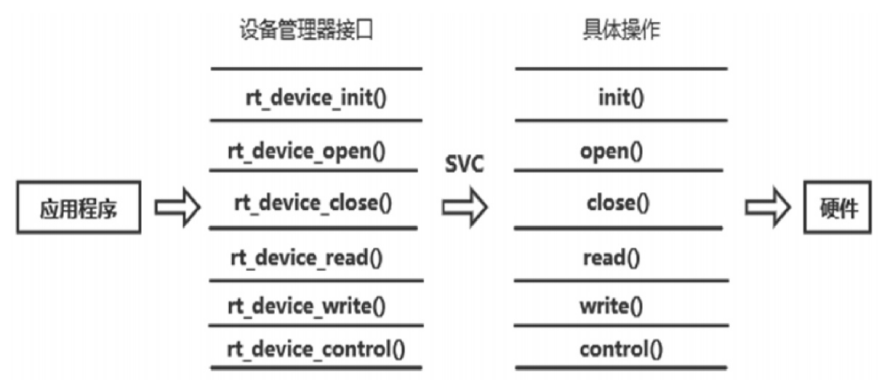
Figure 4 Flowchart of APP Using Driver
In Figure 4, the left side’s rt_device_open() and other functions eventually call the assembly instruction svc 0 to trigger an exception and enter kernel mode. The kernel’s exception handling function will call various functions based on the reason for the triggered exception. Writing a driver mainly involves implementing init, open(), and other functions, which use the structure rt_device_ops to describe each device, defined as follows:
Struct rt_device_ops{/*common device interface*/rt_err_t(* init)(rt_device_t dev);rt_err_t(* open)(rt_device_t dev, rt_uint16_t oflag);rt_err_t(* close)(rt_device_t dev);rt_size_t(* read)(rt_device_t dev, rt_off_t pos, void *buffer, rt_size_t size);rt_size_t(* write)(rt_device_t dev, rt_off_t pos, const void *buffer, rt_size_t size);rt_err_t(* control)(rt_device_t dev, int cmd, void *args);};During serial port porting, based on the chip manual and the board schematic, modify the physical address in the hw_uart_device_uart0_device structure in the serial.c file to 0x40010000, and the interrupt number to 84. The physical address will be converted to a virtual address for upper-level use during runtime. In the rt_err_t uart_configure function, set parameters to receive data using interrupt mode. When an interrupt occurs, use the getc function in rt_uart_ops to read data. Register the structure in the kernel, and the serial port porting based on this device is completed.
3.4 Clock System
The Generic Timer is a hardware implementation of ARM that can achieve a unified programming method. The clock can be divided into two parts: the shared System Counter and the dedicated Timer for each Processor. System Counter: Provides a unified time Timer for all Processors, can set periodic events, and provides interrupt signals to Processors. The clock pulse is generated by hardware timers configured in interrupt trigger mode, and when an interrupt arrives, void rt_tick_increase(void) will be called, notifying the operating system that a system clock has elapsed. Different hardware timer interrupt implementations vary; the following interrupt function uses the STM32 timer as an example.
void SysTick_Handler(void){/* Entering interrupt */rt_interrupt_enter();......rt_tick_increase();/* Exiting interrupt */rt_interrupt_leave();}When an interrupt occurs, rt_tick_increase() will be called in the interrupt, and in this function, the global variable rt_tick will be incremented. Every clock tick value will increase by 1, and the value of rt_tick represents the total number of clock ticks that have elapsed since the system started, that is, the system time. Additionally, every clock tick will check whether the current thread’s time slice has expired and whether any timers have timed out. The clock system can choose PLL output, HSI output, or HSE output. HSI and HSE can be increased by frequency division to PLLSRC, and then multiplied by PLLMUL to be selected as the Generic Timer.[8] Figure 5 is the hardware block diagram of the Generic Timer.
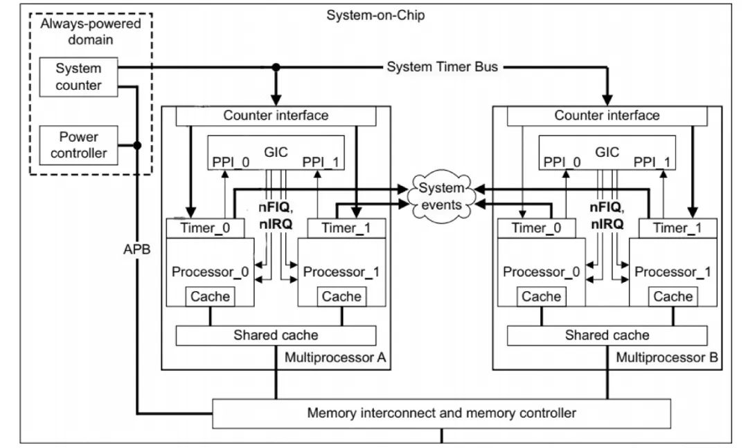
Figure 5 Hardware Block Diagram of Generic Timer
Each Processor has a Timer, and these Timers send periodic interrupts to provide system clocks to the Processor. The Timer needs to use CP15 coprocessor commands to access. The clock can be set for different components as shown in Figure 6.
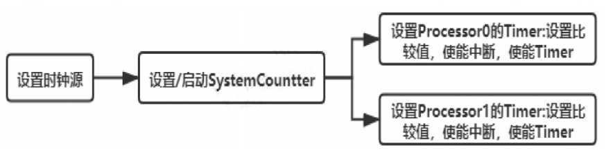
Figure 6 Clock System Diagram
The main tasks completed include: 1) initializing and enabling the timer; 2) setting the interrupt number; 3) calling the kernel-provided tick function; 4) setting the next interrupt; 5) clearing the interrupt.
Part Five
4 Porting Test Results
After completing the above porting work, an image file was created and written into development, along with a program test. The results show that the system works normally and the porting is successful, as shown in Figure 7.
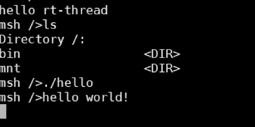
Figure 7 Porting Test Results
Part Six
5 Conclusion
This article describes the porting of the RT-Thread Smart system on the STM32MP1 processor and introduces the porting process. After testing, the system can operate normally. The research in this article contributes to the development of the domestic operating system RT-Thread Smart and provides a solution for the wider application of domestic systems. Future porting can be modified based on specific working scenarios.
References

[1] Lu Xiaojing. Open-source RT-Thread Smart hybrid microkernel operating system helps the rapid development of the domestic embedded industry [J]. Embedded System Applications, 2020(10):92-93.
[2] Zou Ziyu, Mao Xinnong. Porting of real-time operating system RT-Thread on CK520 [J]. Embedded System Applications, 2019(12):58-60.
[3] Zhou Li, Yao Maoqun. Porting and research aimed at Cortex-A8 microprocessors [J]. Computer Technology and Development, 2018(12):179-184.
[4] Wang Qiang, Chen Lan, Hao Xiaoran. A mixed memory system based on memory access behavior address mapping mechanism [J]. Small and Micro Computer Systems, 2014(6):1201-1206.
[5] Ren Keqiang, Wang Chuanqiang. Design of multi-channel serial port driver TFT LCD display system based on STM32F4 [J]. LCD and Display, 2020(5):449-455.
[6] Zhao Xinyue. Research on commonly used interface communication technology for microcontrollers [J]. Digital World, 2020(8):34-35.
[7] Jing Haixia. Analysis of the clock system of STM32 series microcontrollers [J]. Science and Technology Information, 2008(33):511-512.
(Author’s affiliation: China Electronics Technology Group Corporation, 32nd Research Institute, Shanghai 201800)
(This article is authorized for publication by the Journal of Microcontroller and Embedded System Applications, originally published in the 8th issue of 2021)
END
[Click the “blue words” above to follow us for more related content]


Follow us for more exciting content