Hello everyone, I am Xiao Chen. In industrial automation, the accuracy of analog signal acquisition directly affects the stability of the entire control system and product quality.
However, many users often struggle with signal drift issues when using Mitsubishi FX series PLCs for analog signal acquisition.
Today, I will share several practical anti-interference solutions that I have verified in multiple projects to help you solve the annoying problem of analog signals drifting.
Analysis of Causes of Analog Drift
Analog signals in industrial environments are like “sensitive babies,” easily affected by various interferences. These interferences are similar to when you are focused on listening to a friend, and suddenly someone nearby starts making loud noises, disrupting your ability to receive information accurately.
Common sources of interference include:
- Electromagnetic Interference: Transient electromagnetic fields generated when variable frequency drives and high-power motors start and stop.
- Common Ground Interference: Ground potential fluctuations caused by multiple devices sharing a ground line.
- Power Supply Interference: Fluctuations caused by poor power quality.
- Signal Line Coupling: Electromagnetic coupling between parallel power lines and signal lines.
In a project in an injection molding workshop, the pressure sensor readings were inexplicably fluctuating, and it was eventually discovered that the transient current generated by the nearby injection molding machine during startup was interfering with the signal line. This drift not only affected the displayed readings but could also lead to erroneous actions in the control system, potentially causing safety incidents.
Hardware Wiring Optimization Solutions
Correct Wiring Method
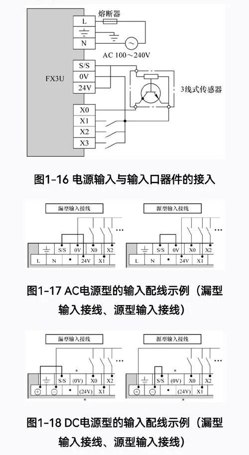
The wiring of the analog module may seem simple, but details determine success or failure. For example, the correct wiring for the Mitsubishi FX3U-4AD analog module is as follows:
Sensor +24V  ──── Power +24V
Sensor Signal+ ──── FX3U-4AD V1+/I1+
Sensor Signal- ──── FX3U-4AD V1-/I1-
Sensor GND   ──── Power GND ──── FX3U-4AD AG
Note: The AG terminal must be connected to the power GND terminal, and a single-point grounding method should be used to avoid forming a ground loop!
Key Anti-Interference Measures
-
Use Shielded Cables: Choose high-quality shielded twisted pairs for analog signals, with the shield grounded at a single point at the PLC end.
-
Wiring Optimization:
- Separate the signal lines from power lines,maintaining a minimum distance of over 20cm.
- When crossing, maintain a 90-degree perpendicular intersection.
- Keep the signal lines as close as possible to the grounded metal cable tray.
- Add Filters: Install an RC filter circuit at the sensor output, as shown in the diagram below:
Sensor Output ──── 100Ω Resistor ──── PLC Input
                  │
                0.1μF Capacitor
                  │
                 GND
There was a student in a water treatment project who laid nearly 50 meters of cable between the sensor and PLC, resulting in severe signal drift. After I suggested he replace it with a shielded cable and install the above RC filter circuit, the drift issue was immediately resolved.
Software Filtering Techniques
In addition to hardware measures, software filtering is equally important. The Mitsubishi FX series PLC can implement effective filtering algorithms through programming.
Average Filtering Example Code
* Average filtering program, suitable for Mitsubishi FX series PLC
* Continuously read 10 times and average the analog value to eliminate random interference
* D0: Original analog data
* D10-D19: Sampling buffer
* D100: Filtered result

LD     M8000        ; Normally open contact, always ON
MOV    D0     D10   ; Store current value in D10
MOV    D10    D11   ; Shift data back
MOV    D11    D12
MOV    D12    D13
MOV    D13    D14
MOV    D14    D15
MOV    D15    D16
MOV    D16    D17
MOV    D17    D18
MOV    D18    D19
ADD    D10    D11   D20   ; Accumulate 10 data
ADD    D20    D12   D20
ADD    D20    D13   D20
ADD    D20    D14   D20
ADD    D20    D15   D20
ADD    D20    D16   D20
ADD    D20    D17   D20
ADD    D20    D18   D20
ADD    D20    D19   D20
DIV    D20    K10   D100  ; Calculate average
Median Filtering Algorithm
For pulse interference, average filtering may not be effective, and median filtering can be considered:
* Median filtering program example
* Collect 9 samples, sort, and take the middle value
* D200-D208: Store 9 sampling values
* D300: Sorted result
* D350: Final median result

* Sorting algorithm code omitted here
* Sorted results are stored in D200-D208

MOV    D204   D350  ; Take the middle value D204 as the filtering result
In a temperature control project, I initially used average filtering but encountered occasional spike interference. After switching to median filtering, the system stability significantly improved, and the temperature control accuracy increased from ±2℃ to ±0.5℃.
Parameter Adjustment Optimization
The Mitsubishi FX series analog modules have several parameters that can be adjusted to improve anti-interference capability:
- Sampling Average Count: Set through special registers, increasing the average count can enhance anti-interference capability but will reduce response speed.
* Set the average count for CH1 channel to 16 times
MOV    K16    D8602
- Input Filter Constant: Can be adjusted based on site conditions.
* Set the filter constant for CH1 channel to 20%
MOV    K20    D8610
- Sampling Rate and Resolution Balance: Reducing the sampling rate can improve anti-interference capability.
* Set to low-speed high-precision mode
M8002
MOV    H1111  D8609  ; Set all channels to low-speed high-precision mode
Important Note: Parameter adjustments need to be tested on-site to find the best balance between interference suppression and response speed!
Case Study Analysis
Once, in a temperature control system project at a steel plant, the thermocouple signal was inexplicably drifting, causing chaotic temperature control. After investigation, it was found that the issues were multifaceted:
- The signal line did not use shielded cables.
- The cable was laid parallel to high-voltage power lines.
- The grounding system had multiple grounding points, forming a ground loop.
- The software filtering algorithm was not robust enough.
After implementing the following comprehensive measures, the problem was completely resolved:
- Replaced with high-quality shielded twisted pairs.
- Re-planned cable paths, away from interference sources.
- Changed to single-point grounding to eliminate ground loops.
- Implemented a combination algorithm of median filtering and clipping filtering.
- Adjusted the module to low-speed high-precision mode.
Comparison before and after the modification:
- Before modification: Temperature readings fluctuated ±15℃, with poor control accuracy.
- After modification: Temperature readings stabilized within ±0.8℃, with significantly improved control accuracy.
Common Issues and Troubleshooting Techniques
-
How to quickly determine if it is an interference issue or a sensor fault?
- Use a multimeter to directly measure the sensor output and observe if there are fluctuations.
- Try shorting the PLC analog input (using precision resistors) to see if there are still fluctuations.
- Test at different times (e.g., when production equipment is stopped) to compare data fluctuation conditions.
How to deal with occasional spike interference?
- Add “clipping filtering” in the software to ignore values that exceed reasonable ranges.
- Check if there are high-power devices starting and stopping on-site, and consider adding power supply filters.
How to improve anti-interference capability without affecting response speed?
- Combine hardware and software measures, reducing extreme parameters of single measures.
- Consider using advanced algorithms like Kalman filtering to balance response speed and filtering effects.
Practical Protection Checklist
Here is a practical “Analog Anti-Interference Checklist” that can be used as a reference in projects:
-
Hardware Check:
- Use shielded twisted pairs.
- Shielding layer grounded at a single point.
- Signal lines separated from power lines.
- Reasonable wiring to avoid loops.
- Install necessary filters.
Software Check:
- Implement digital filtering algorithms.
- Choose appropriate filtering methods based on signal characteristics.
- Set reasonable sampling parameters.
- Write logic for handling outliers.
System Check:
- Ensure the entire system is well grounded.
- Check power quality.
- Conduct EMC environment assessment.
Practical operation suggestion: Start with hardware to solve interference issues, which is usually more fundamental than software filtering. You can first use an oscilloscope to observe the original signal waveform, assess interference characteristics, and then implement targeted protective measures.
First, focus on the grounding system and wiring specifications, then consider other anti-interference measures. When designing the analog acquisition system, it is advisable to leave ample adjustment space for anti-interference to prepare for on-site debugging.
No matter which solution is adopted, it ultimately needs to be verified in the actual working environment,long-term testing is necessary to ensure the effectiveness and stability of the solution.
By effectively solving the interference issues in the analog acquisition system, you will find that subsequent implementation of control algorithms becomes much easier.